
Page 245 - Radar Technology Encyclopedia
P. 245
235 LENS lens, bootlace-type
control signals, the lens is referred to as a controllable lens.
Lenses are referred to as dielectric, metal-plate, and metal-air,
Table L1 depending upon the lens material used. Lenses are catego-
Comparison of Reflector and Lens Collimators rized as focusing, reflection, and divergent based on the task
accomplished. Focusing lenses are those converting a wave
Feature Reflector Lens with a nonplanar front into one with a plane phase front.
Those that rereflect electromagnetic waves striking them in a
Degrees of freedom 1 Up to four* given direction are referred to as reflection lenses. Lenses
with a heterogeneous dielectric with special profile convert-
Aperture blockage Present Absent
ing a spherical wave into a wave with any form of phase front
are called divergent lenses. Lenses are used widely in vari-
Losses Lower Higher
able-purpose radar antennas. Their use in millimeter-wave-
Chromatic aberration No Yes band antennas is very promising. (See ANTENNA, lens).
Phased array antennas in the form of transmission lenses
Supporting structures Simpler More complex made up of phase-shifting elements are also used in multitar-
get and multifunction radars. (See FEED, antenna.) AIL
Weight and size Less More
Ref.: Zelkin (1974), pp. 27–191; Johnson (1984), Ch. 16.
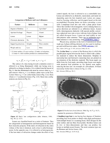
* (1) inner surface, (2) outer surface, (3) index of refraction, The Archer lens is a variant of the Rotman lens in which the
(4) inner-vs.-outer radiator position (in constrained lens). parallel-plate region between the feeds is filled with a dielec-
tric material to reduce the linear dimensions. Stripline or
microstrip lens and feed-port connecting lines are printed on
n = e = cv ¤ > 1, and n = cv ¤ < 1 an extension of the dielectric material. The beam angle can
2 2 f 2 f
differ from the feed angle, providing large beam scan angles
The surface of a lens facing toward a radiation source is with practical feed positions or, for limited scan angles,
referred to as being illuminated, while one facing away is reducing the lens size. An example of a 20-radiator, 16-beam
referred to as being in shadow. It is evident from the layout of microstrip Archer lens is shown in Fig. L3. SAL
Fig. L1 that the illuminated side must be convex when n > 1 Ref.: Johnson (1984), pp. 20–21.
2
and concave when n < 1, to obtain a plane wave in the lens.
2
Lenses where n > 1 are called delay lenses (Fig. L1a); those
2
where n < 1 acceleration lenses (Fig. L1b). Basic lens config-
urations are shown in Fig. L2.
Rotational lens, n > 1 Rotational lens, n < 1
(a) (b)
Pillbox
Waveguide array feed
Cylindrical lens, n > 1 Cylindrical lens, n < 1 Figure L3 Archer lens (from Johnson, 1984, Fig. 16.17, p. 16.21,
(c) (d) reprinted by permission of McGraw-Hill).
Figure L2 Basic lens configurations (after Johnson, 1984, A bootlace-type lens is one having four degrees of freedom,
Fig. 16.1, p. 16.3). providing four focal points to obtain wide-angle performance
with multiple beams or a scanning beam. Most designs fix the
Lenses are classified based on a series of features. They
outer surface and use three focal points. Bootlace lenses can
are categorized as homogeneous and heterogeneous based on
be two- or three-dimensional, and they can produce fan
their dielectric property. If the index of refraction in the entire
beams or multiple pencil beams. The most common types are
volume of the lens is identical, such a lens is called homoge-
the Rotman and Archer lenses. SAL
neous. In the opposite case, it is referred to as heterogeneous.
If the lens index of refraction changes under the effect of any Ref.: Johnson (1984), pp. 16.19–16.22.