
Page 295 - Radar Technology Encyclopedia
P. 295
285 navigation, range-finding NAVIGATOR, doppler
intersection of two lines of position. To eliminate the ambigu-
ity, additional data are used with the crude accuracy sufficient
to determine one of two intersection points as the true loca-
tion. As the achievable accuracy of range measurement can
be very high, the coordinates of the object can be determined
with high accuracy. The DME system is an example of range-
finding navigation system.
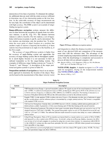
Range-difference navigation systems measure the differ-
ence in time between the reception of signals from two refer-
ence stations: A and B (Fig. N3). The distance between
1
stations is called a baseline. For two stations, a set of hyper-
bolas with focuses in points A and B can be determined. The
1
two stations can determine only the position line. To deter-
mine the exact point of object location on a position line
another couple of stations is required; the baseline d of these Figure N3 Range-difference navigation method.
2
stations must be positioned at an angle a to the baseline d of
1
the first couple. and integration to obtain the distance traveled, or on measure-
ment of any physical field and comparison of the measure-
The accuracy of range-difference systems is higher than
ment data with the reference data. The advantage of the
the accuracy of angle-finding system and approaches the
systems employing nonposition methods is autonomous oper-
accuracy of range-finding system. But its throughput capabil-
ation, while the disadvantage is complexity and necessity to
ity is much higher, because it is not necessary to have an
process all data with an onboard computer. AIL
onboard transmitter as for the range-finding system. The
examples of difference-range finding systems are “Loran-A,” Ref.: Skolnik (1970), p. 16.33; Kazarinov (1990), pp. 182–194; Belavin
(1967), pp. 5–62; Sosulin (1992), pp. 11–15
“Loran-C,” and “Omega.” A description of the major posi-
tional navigation systems is given in Table N1. NAVIGATOR, doppler. A doppler navigator is a CW radar
used for navigation, relying on the nonpositional method.
Nonposition methods of navigation are based on an autono-
(See NAVIGATION, radio.) SAL
mous approach to determine the location of the object. They
Ref.: Skolnik (1990), p. 14.37.
can be based on the measurement of the object velocity vector
Table N1
Major Positional Navigation Systems
System Description
VOR VHF Omnidirectional Range. A ground transmitter radiates CW signals on one of the even frequencies between 108
and 118 MHz. A cardioid antenna pattern rotates at 30 Hz, producing an AM signal at 30 Hz in the airborne receiver.
A 30-Hz reference frequency is radiated as FM, ± 480 Hz on a 9,960-Hz subcarrier. The bearing is measured as a
function of the phase between the FM and the AM modulations as read by the airborne receiver.
DVOR Doppler VOR. A wide-aperture VOR to reduce site error. It uses a 15m diameter circular array of antennas to gener-
ate the variable phase, and the reference phase is transmitted by a single, central antenna. The format is compatible
with standard VOR receivers.
TACAN TACtical Air Navigation. Constant duty cycle DME beacon to which a rotating cardiod antenna pattern plus a 9-
lobed pattern is added. It generates a 15-Hz coarse bearing and 135-Hz fine bearing in the aircraft receiver.
DME Distance-Measuring Equipment. The airborne interrogator transmits about 30 pulse pairs per second on one of 126
channels between 1,025 and 1,150 MHz. The ground transponder replies on one of 126 channels between 962 and
1,027 or 1,151 and 1,213 MHz. The airborne indicator reads transmit-to-receive time delay on a meter calibrated in
nautical miles.
LORAN A, C LOng RAnge Navigation. Pulse of 45 ms duration are transmitted by a master station on a carrier of 20 to 34 MHz,
and repeated by a slave station some 450 km away. An aircraft, using an oscilloscope display, measures the differ-
ence in time of arrival and computes its position by using two or more slave stations. In comparison with LORAN-
A, the LORAN-C system uses the same basic principle, but with a carrier at 100 kHz where ground-wave propaga-
tion is possible to long ranges.
Omega A range-difference system using high-power transmitters with time-shared CW signals at about 10 kHz. The base-
lines and operational ranges are about 9,000 km.