
Page 292 - Radar Technology Encyclopedia
P. 292
MTI, limitations to performance MTI, PRF-diversity 282
ln 2 f r
×
s = ------------ ---
fa p n
is the scanning modulation spectral spread of clutter, and n is
the number of hits per scan. Equation (1) shows the maximum
attainable improvement factor against clutter with a Gaussian
spectrum centered at zero frequency.
Staggering of the PRF results in a limit to improvement
factor due to unequal time spacing between the clutter sam-
ples:
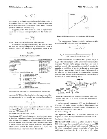
2 Figure M31 Phasor diagram of noncoherent MTI detector.
æ 2.5n ö
I = -----------
ms è g 1– ø .
The improvement factors for single- and double-delay
where g is the ratio of maximum to minimum PRF.
noncoherent MTI using a square-law detector are
The sources of equipment instability are given in Table
2
2
M6, with the corresponding limits to improvement factor in I m1 = ------------------------------- » ---- 2
2
decibels. To find the attainable improvement factor in the 1 – exp – ( z ) z
Table M6 21 () 1
I m2 = ------------------------------------------------------------------------------------------------ » ----
2
2
Instability Limitations in MTI 1 – ( 4 3 ¤ ) exp – ( 2z ) 1 3 ¤( ) exp – ( 4z ) z 4
+
In the conventional noncoherent MTI system, targets in
range cells containing no clutter are lost for want of a phase
reference. Various clutter gating procedures are used to
enable a normal video channel in such cells, bypassing the
canceler to avoid loss of targets. A alternative noncoherent
MTI detector uses the hard-limited output of adjacent cells as
the reference to a phase detector, such that moving targets are
detected in the absence of clutter through the random phase of
noise in the reference cells (Fig. M32).
(from Skolnik, 1990, Table 15.4, p. 15.42, reprinted by permission of McGraw-Hill)
presence of N different limiting factors, the improvement fac-
tors are converted to power ratios and combined according to Figure M32 Phase-detection circuit for noncoherent MTI (from
Skolnik, 1970, Fig. 59, p. 17.54, reprinted by permission of
N
McGraw-Hill).
– 1 1
I m = å -------
I Advantages of noncoherent MTI are simplicity and its
mi
i = 1 inherently adaptation to moving clutter. Disadvantages are
where the individual factors include those shown in Table M6 reduced improvement factor and inability of most types to
plus I ma and I from inherent clutter spread, antenna scan- operate in the absence of clutter. DKB
ms
ning, and PRF stagger. SAL
Ref.: Skolnik (1980), p. 138.
Ref.: Skolnik (1980), p. 129, (1990), p. 15.41.
The optimum MTI uses an Urkowitz (inverse) filter
Noncoherent MTI uses clutter echoes from the target region response to whiten the output interference spectrum. DKB
as the phase (velocity) reference for detection before the can-
Ref.: Barton (1988), p. 236.
celer or filter. One common form of noncoherent MTI uses an
PRF-diversity MTI produces an effect similar to stagger-
envelope detector at the receiver output, the output amplitude
PRF MTI, except that sequential bursts of pulses at each PRF
of which varies at the target doppler shift as the signal phasor
are transmitted, received, and batch-processed. Addition of p
rotates around end of the clutter phasor (Fig. M31). This
fill pulses to each batch supports cancellation of clutter from
amplitude change component passes the canceler.
ambiguous range intervals, R < R < (p + 1)R , where
u
u
c