
Page 289 - Radar Technology Encyclopedia
P. 289
279 MOVING-TARGET DETECTOR (MTD) MOVING TARGET INDICATION (MTI)
The MTI precanceler eliminates most of the fixed clutter, signals of the next interval. The result is cancellation of fixed
reducing the dynamic range required in subsequent process- targets and passage of targets with pulse-to-pulse change in
ing. The doppler filter bank is typically based on the FFT detected amplitudes.
algorithm, providing the following advantages over a delay- The resultant video signal is
line canceler: (1) the signal-to-noise ratio is improved by
vt () ksin= ( 2p f t – f )
0
d
coherent integration within each of the n filters, whose band-
and that delayed from the previous transmission is
width will be 1/n that of the canceler; (2) doppler frequency
measurement is available, based on the filter number in which vt – T ) ksin= [ 2pf t – T ) – f ]
(
(
d 0
detection occurs; (3) the filter bandwidth can be adjusted by
The resulting canceler output is
amplitude or frequency weighting (windowing), giving better
æ
range sidelobe reduction; (4) adaptive thresholding can be Dv = A cos 2pf t – T ö f
--- –
D d è 2 ø 0
applied to each filter, permitting rejection of moving clutter
(e.g., weather clutter). where k is the amplitude of the video signal, f is the doppler
d
The use of burst-to-burst PRF diversity is necessary to frequency, f is the initial phase shift, and T is the pulse repe-
0
fill blind speeds that fall within the target velocity region, and tition interval. The amplitude of the canceler output is
it provides a means of rejecting multiple-time-around (range- A = 2ksin ( pf T )
D d
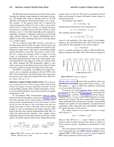
ambiguous) target echoes. The adaptive thresholding applies and it is a periodic function of T and f , called the MTI (fre-
d
separate thresholds to each filter: the nonzero velocity chan- quency) response (Fig. M28). This is the classical response of
nels use a range-cell-averaging CFAR to adapt to moving
clouds of precipitation, while the zero-velocity channel
threshold is generated by the clutter map, which applies a sep- 2
arate threshold for each range cell. In the zero-velocity chan-
nel, which bypasses the MTI precanceler, targets at zero Amplitude
radial velocity and at the blind speeds can be detected if they 1
exceed by a sufficient margin the clutter stored in the map.
The MTD is essentially a low-PRF pulsed doppler pro-
0 1 0 1 2 3 4 5
cessor, and was originally developed in the mid-1970s at the Frequency (units of 1/T)
MIT Lincoln Laboratory. The initial design used a three-pulse
precanceler and an eight-pulse doppler filter bank. DKB, SAL Figure M28 MTI frequency response.
Ref.: Schleher (1991), pp. 37–52.
a single-delay canceler. It shows that cancellation will occur
MOVING-TARGET INDICATION (MTI). MTI is the pro-
not only for zero-velocity targets but for those with f = i/T.
cess of rejecting fixed or slowly moving clutter while passing di
The speeds v = lf /2 at which this undesired cancellation
echoes from targets moving at significant velocities. In most i di
occurs are termed blind speeds.
cases the MTI is sensitive only to radial components of veloc-
To improve this simple response, more complex cancel-
ity, but area MTI techniques can provide sensitivity to angular
ers can be used: those of the three-pulse, or occasionally the
components as well.
four-pulse type; cancelers with feedback (infinite-impulse-
In conventional MTI, discrimination between echoes
response filters); or more complex filters operating on range-
from fixed and moving targets is based on the doppler effect.
gated receiver outputs. The most common MTI systems pass
The filter technique can be realized either in the time or fre-
video (baseband) pulses through the cancelers, using parallel
quency domain. Implementation in the time domain is based
channels for in-phase (I) and quadrature (Q) phase-detected
on the fact that the phase of the fixed target echo does not
components. Other approaches pass intermediate frequency
change from pulse to pulse, while that of the moving target
(IF) signals through a vector canceler.
changes at a rate corresponding to the doppler frequency. This
The voltage response of an m-pulse canceler to a target
leads to the delay-line canceler implementation (Fig. M27), in
with velocity v is
which the phase-detected (bipolar) video signals (whose
m
v =
amplitudes depend on their phase angles) are fed into a delay H () [ 2 sin ( pvv ¤ b )]
m
equal to the pulse repetition interval and subtracted from the
shown in Fig. M29 for m = 1 and 2. Failure to center the
rejection notch on clutter moving with velocity Dv leads to a
Bipolar video Unipolar video
clutter response H (Dv), degrading the performance of the
to indicator m
Delay line
Receiver Subtractor Full-wave system.
T = 1/prf circuit rectifier
The wide rejection notch formed for m > 1 causes serious
loss in target detection (see LOSS, velocity response) unless
Figure M27 MTI receiver with delay-line canceler (after staggered PRF or PRF diversity is used. A typical staggered
Skolnik, 1980, Fig. 4.4, p. 104). PRF velocity response is shown in Fig. M30.