
Page 287 - Radar Technology Encyclopedia
P. 287
277 monopulse, amplitude-amplitude monopulse, phase-phase
ence reverts to zero. The direction-finding characteristic of the vertical plane and the phase method in the horizontal
this system is plane.
Two phase detectors, one forming an elevation error sig-
S q() 2mq
=
nal and the other forming an azimuth error signal, are shown,
where m is the slope of the antenna pattern.
to extract angular information relative to each coordinate at
A shortcoming of a system with a pulse-amplitude dis-
receiving channel input. A difference signal is supplied to the
criminator is the requirement to maintain exact amplitude
azimuth phase detector with a 90°phase shift relative to the
match in the amplifier responses. AIL
overall signal, which is the reference signal. The direc-
Ref.:Sherman (1984), Ch. 5; Leonov (1984), p. 66.
tion-finding response is
------ sin
=
S q() K tan æ pL q ö
pd è l ø
where K is the phase detector transmission factor q is the
pd
deviation of the beam peak from the equisignal direction, and
l the wavelength.
s
i
An advantage of monopulse systems with combined
direction finding is that, for direction finding in two planes, it
turned out to be possible to work with just two beams and two
interconnected channels with one waveguide bridge at their
input, something especially important for airborne radar
equipment, where weight and size are of primary signifi-
cance. AIL
Ref.: Barton (1974), pp. 269–275; Leonov (1986), p. 95.
(a)
Figure M21 Sum-and-difference angle discriminators: with
(a) combined, and (b) separate formation of the magnitude and
sign of the error signal, and (c) with normalization by the sum
signal at video frequency (after Leonov, 1986, Fig. 1.5, p. 11).
Log IF amp Env det
T/R LO Subtract Error signal
amplifier
Log IF amp Env det Antenna
Transmitter
control system
(b)
Figure M22 Radiation patterns and block diagram of an
amplitude-amplitude monopulse system (after Leonov, 1986,
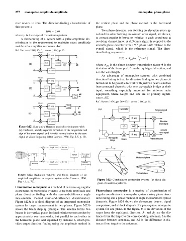
Figure M23 Combination monopulse system: (a) block dia-
Fig. 4.1, p. 76).
gram, (b) antenna patterns.
Combination monopulse is a method of determining angular
coordinates in monopulse systems using both amplitude and Phase-phase monopulse is a method of determination of
phase direction finding with the sum-and-difference angle angular coordinates in monopulse systems using phase direc-
measurement method (sum-and-difference discriminator). tion finding and a phase method of angle measurement (phase
Figure M23a is a block diagram of an integrated monopulse detector). Figure M24 shows the elementary beams, signal
system for target measurement in two planes. Figure M23b comparison, and a block diagram of a phase-phase monopulse
shows the beam shaping principle. The antenna forms two system for one plane. In the figure, q is the deviation of the
beams in the vertical plane, inclined relative to one another by target from the equisignal direction, R and R are the dis-
1
2
approximately one beamwidth, but parallel to each other in tances from the target to the corresponding antennae, L is the
the horizontal plane, and separated by distance L, which pro- distance between antennas, and DR is the difference in dis-
vides target direction finding using the amplitude method in tances from target to the antennas.