
Page 283 - Radar Technology Encyclopedia
P. 283
273 modulator, line-type [or linear] modulator, pulse
duration of the formed pulse is equal to twice the delay time etition period to a voltage close to the constant voltage of the
in the line. In this circuit a hydrogen thyratron is generally supply source. The discharge time constant is selected on the
used, ensuring a high slope of the wave front of the pulse. basis of requirements on the pulse shape and on the stability
IAM of the carrier frequency. Usually an acceptable change of
Ref.: Davydov (1984), p. 40; Skolnik (1990), p. 4.33. voltage during the starting pulse is several percent. The shape
of the trailing edge of the pulse is determined by the period of
A magnetic modulator is a pulse modulator with a switch in
oscillations arising after closure of the commutator, in the cir-
the form of a nonlinear inductance coil. Nonlinear induc-
cuit formed by the charge reactor the parasitic capacitances of
tances used as coils are transformers with ferrite cores having
the circuit. To compensate for undesirable oscillations, a
a hysteresis curve of minimum area with the maximum possi-
damping circuit is used that contains a diode of opposite
ble saturation inductance. Operation of the modulator is based
polarity of the source (see Fig. M14).
on the property of sharp increase in the inductance of the coils
These modulators have good timing stability for both
of such a transformer at magnetization current values corre-
leading and trailing edges of the pulse. The basic drawbacks
sponding to the top and bottom saturation regions.
include their large dimensions and mass.
Magnetic modulators are divided into two classes: ac
Modulators with partial discharge of the capacitive stor-
modulators, whose pulse repetition frequency is equal to or a
age device are widely used in aircraft radars and secondary
multiple of the frequency of the supply voltage, or dc modula-
radars, because of their capability of generating pulses whose
tors (thyristor-magnetic modulators) whose pulse repetition
duration and PRF can be efficiently changed without switch-
frequency is determined by the external triggering devices.
ing to high-voltage circuits, and the capability of forming
Modulators of the first type are most frequently used in
two- and three-pulse code messages. IAM
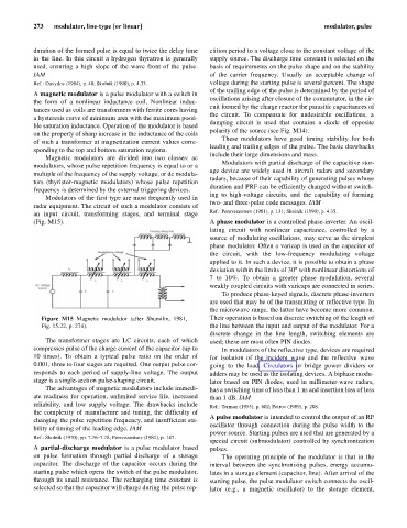
radar equipment. The circuit of such a modulator consists of
an input circuit, transforming stages, and terminal stage Ref.: Perevezentsev (1981), p. 131; Skolnik (1990), p. 4.35.
(Fig. M15). A phase modulator is a controlled phase-inverter. An oscil-
lating circuit with nonlinear capacitance, controlled by a
source of modulating oscillations, may serve as the simplest
phase modulator. Often a varicap is used as the capacitor of
the circuit, with the low-frequency modulating voltage
applied to it. In such a device, it is possible to obtain a phase
deviation within the limits of 30° with nonlinear distortions of
7 to 10%. To obtain a greater phase modulation, several
weakly coupled circuits with varicaps are connected in series.
To produce phase-keyed signals, discrete phase-inverters
are used that may be of the transmitting or reflective type. In
the microwave range, the latter have become more common.
Figure M15 Magnetic modulator (after Shumilin, 1981, Their operation is based on discrete switching of the length of
Fig. 15.22, p. 274). the line between the input and output of the modulator. For a
discrete change in the line length, switching elements are
The transformer stages are LC circuits, each of which used; these are most often PIN diodes.
compresses pulse of the charge current of the capacitor (up to In modulators of the reflective type, devices are required
10 times). To obtain a typical pulse ratio on the order of for isolation of the incident wave and the reflective wave
0.001, three to four stages are required. One output pulse cor- going to the load. Circulators or bridge power dividers or
responds to each period of supply-line voltage. The output adders may be used as the isolating devices. A biphase modu-
stage is a single-section pulse-shaping circuit. lator based on PIN diodes, used in millimeter-wave radars,
The advantages of magnetic modulators include immedi- has a switching time of less than 1 ns and insertion loss of less
ate readiness for operation, unlimited service life, increased than 1 dB. IAM
reliability, and low supply voltage. The drawbacks include Ref.: Terman (1955), p. 602; Petrov (1989), p. 208.
the complexity of manufacture and tuning, the difficulty of
A pulse modulator is intended to control the output of an RF
changing the pulse repetition frequency, and insufficient sta-
oscillator through connection during the pulse width to the
bility of timing of the leading edge. IAM
power source. Starting pulses are used that are generated by a
Ref.: Skolnik (1970), pp. 7.76–7.78; Perevezentsev (1981), p. 147.
special circuit (submodulator) controlled by synchronization
A partial-discharge modulator is a pulse modulator based pulses.
on pulse formation through partial discharge of a storage The operating principle of the modulator is that in the
capacitor. The discharge of the capacitor occurs during the interval between the synchronizing pulses, energy accumu-
starting pulse which opens the switch of the pulse modulator, lates in a storage element (capacitor, line). After arrival of the
through its small resistance. The recharging time constant is starting pulse, the pulse modulator switch connects the oscil-
selected so that the capacitor will charge during the pulse rep- lator (e.g., a magnetic oscillator) to the storage element,