
Page 282 - Radar Technology Encyclopedia
P. 282
modulator, active-switch modulator, line-type [or linear] 272
They are subdivided into three basic types: cathode modula- opposing connection of high-frequency varicaps is sometimes
tors, anode modulators, and grid modulators. The first control used.
the full power of a beam of an oscillator tube either directly or A frequency modulator based on phase modulation is
through a connecting circuit. The anode pulse modulator pro- distinguished by its capability of using an independent high-
vides a voltage equal to the full voltage of the tube beam, and stable local oscillator, but the frequency deviation of the sig-
the current is determined only by the charge of the capacitors nal at the output of the modulator does not exceed 1%. IAM
of the circuit at the start and end of the pulse, since the modu- Ref.: Terman (1955), p. 601; Petrov (1989), p. 203; Shumilin (1981), p. 227.
lating anode consumes a low current during the pulse. The
An ion-switch modulator is a linear modulator using hydro-
output voltage of the pulse modulators for RF tubes with a
gen thyratrons or ignitrons as switches. Modulators operate in
controlling grid is much less, allowing the use of low-voltage
a discharge mode using lines with capacitive reactance as the
components and circuits.
storage devices. Modulator circuits are classified based on the
An anode pulse modulator makes it possible to produce
type of power source into modulators with dc or ac charging.
an exceptionally flat pulse output. Grid modulators are
The latter are used in those cases when the modulating pulse
marked by low parasitic capacitance effects and are especially
repetition frequency is synchronous with the frequency of the
suited for forming radar pulse trains.
supply line, and the modulators themselves synchronize the
A battery of capacitors with dimensions determined by
radar. Modulators supplied from a dc source are more com-
the permissible droop of the pulse peak are used as the stor-
mon.
age device of active modulators. Compared with linear modu-
In terms of storage circuits, we distinguish between mod-
lators, modulators with active switches provide a better shape
ulators that use one (Fig. M14) or many delay lines. An
of pulses, due to the absence of special circuits containing
increase in the number of delay lines makes it possible to
elements with lumped parameters pulse shaping, which limit
reduce the supply voltage of the modulator by a factor of two
the rise time and create intrapulse ripple. IAM
or more in comparison with those using a single delay. IAM
Ref.: Skolnik (1970), pp. 7.78–7.87, (1990), p. 4.32.
Ref.: Skolnik (1990), p. 4.33; Rakov (1970). Vol 2, p. 86.
A complete-discharge modulator is one based on pulse
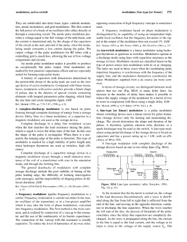
A line-type [or linear] modulator is a pulse modulator
forming through complete discharge of energy from a storage
whose switching device uses a linear circuit for pulse forma-
device. Delay lines in a linear modulator, or a capacitor in a
tion (storage device) only for starting and maintaining dis-
magnetic modulator, are used as the storage device.
charge. The circuit determines the shape and duration of the
Complete discharge in a delay line modulator occurs
pulses. A thyratron, ignitron, electron tube, thyristor, or a
when the line matches the load resistance during the pulse,
spark discharger may be used as the switch. A line-type mod-
which is equal to twice the delay time of the line. In this case
ulator using partial discharge of the storage device is based on
the shape of the pulse is rectangular. When there is a mis-
capacitors and has a power rating up to 1 kW, with an effi-
match, the training edge of the pulse is distorted. This type of
ciency of 40 to 70%.
modulator is marked by a high stability of pulse length and,
A line-type modulator with complete discharge of the
when hydrogen thyratrons are used as switches, high effi-
storage devices based on one or two delay lines (Fig. M14).
ciency.
Complete discharge of a capacitive storage device in a
magnetic modulator occurs through a small inductive resis-
tance of the coil of a transformer with core in the saturation
mode, and through the forming line.
The general drawbacks of modulators with complete
storage discharge include the poor stability of timing of the
pulse leading edge, the difficulty of forming interrogative
code messages, and the impossibility of shaping pulses of dif-
ferent durations. IAM
Figure M14 Line-type modulator (after Davydov, 1984,
Ref.: Glasoe (1948) Part II; Perevezentsev (1981), p. 136; Davydov (1984),
Fig. 2.6, p. 41).
p. 41.
At the moment that the thyratron is turned on, the voltage
A frequency modulator applies frequency modulation to a
in the load decreases discontinuously and a wave is distrib-
carrier. Frequency modulation is carried out either in the mas-
uted along the line from left to right that is reflected from the
ter oscillator of the transmitter, or in a low-power amplifier
end of the line, and moving in the opposite direction, contin-
where it may take the form of phase modulation, converted
ues to discharge the line capacitors. When the wave reaches
into frequency modulation. The first method is the most com-
the left end of the line, the process of formation of the pulse
mon, and is realized by connection of a varicap to the resona-
concludes, since the delay-line capacitors are completely dis-
tor and the use of the nonlinearity of its barrier capacitance.
charged. As the wave is propagated along the line, the current
The connection of the varicap with the resonator is usually
in the line is equal to the load current, and the voltage at its
capacitive. To reduce the level of harmonics of an even order,
input is close to the voltage of the supply source E . The
a