
Page 286 - Radar Technology Encyclopedia
P. 286
MONOPULSE monopulse, amplitude-amplitude 276
difference signal determines the magnitude of the angular off- Typically, in practice only four of them are used: ampli-
set from the null axis and the sign of the difference indicates tude-amplitude (AA), phase-phase (PP), amplitude sum-and-
the direction of the target. difference (ASD), and phase sum-and-difference (PSD).
In the phase-comparison system, the target angle is deter- The accuracy of monopulse angle-sensing is much better
mined by the comparison of the signals received by a pair of than for conical scanning systems and it is not sensitive to
antennas (Fig. M18). The difference between the paths from amplitude fluctuations (random variations in RCS). Although
the antenna phase centers to the target, DR = lsinq, ves the a monopulse system requires two independent channels for
gi
l
R
/
si
l
)
phase difference Df = 2p/l = (2pn q, where l is the each coordinate and it is more complicated, it has become the
wavelength, so the target angle is basic angle sensing technique for precision tracking radars.
q = arcsin (2np/k ) AIL
l
where n = 0, 1, ... , and k = 2p/l is the wave number. The Ref.: IEEE (1993), p. 821; Leonov (1986).
l
presence of factor n causes measurement ambiguity that can
be overcome by the proper choice of displacement between
the phase centers of the antennas. In combination systems,
both amplitudes and phases of the received signals are used to
get the information about the target angle.
Figure M18 Geometry of phase-comparison monopulse (after
Leonov, 1986, Fig. 1.1, p. 3).
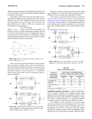
Figure M20 Phase angle discriminator: (a) with limiting IF
There are only three possible methods of angle discrimi- amplifiers; (b) with AGC (after Leonov, 1986, Fig. 1.4, p. 10).
nators realization: amplitude, phase, and sum-and-difference.
The block diagrams of these discriminators are shown in Figs.
Table M5
M19, M20, and M21. Since each of these may be applied in Classes of Monopulse Systems
amplitude-comparison, phase-comparison, or combination
systems, there are nine basic classes of monopulse systems as Method of Basic classes of monopulse sensing
shown in Table M5. measurement systems for three types of angle sensing
(type of angle Amplitude Phase Combination
discriminator) (A) (P) (C)
Amplitude (A) AA PA CA
Phase (P) AP PP CP
Sum and difference ASD PSD CSD
(SD)
(from Leonov, 1986, Table 1.1, p. 7)
Amplitude-amplitude monopulse is a method of determina-
tion of angular coordinates in monopulse systems using
amplitude direction finding and an amplitude method of mea-
surement of an angle (pulse-amplitude discriminator). Figure
M22 shows the block diagram of an amplitude-amplitude
monopulse system for target direction finding in one plane.
The difference in the amplitudes of received signals
defines target deviation from the equisignal line. The sign of
this difference characterizes direction and displacement of the
Figure M19 Amplitude angle discriminator: (a) with logarith-
equisignal direction relative to the target. When the equisig-
mic IF amplifiers; (b) with normalization of the sum at video
nal direction coincides with the target, the amplitudes of the
frequency (after Leonov, 1986, Fig. 1.3, p. 9).
signals received by both patterns are equal, while their differ-