
Page 290 - Radar Technology Encyclopedia
P. 290
MOVING TARGET INDICATION (MTI) MTI, clutter referenced 280
Ref.: IEEE (1993), p. 824; Skolnik (1970), Ch. 17, (1980), pp. 101–150;
Bakulev (1986); Schleher (1991).
Adaptive MTI uses a variable rejection notch that changes
its center velocity (and sometimes its width) in response to
the velocity spectrum of the average clutter in resolution cells
surrounding the target detection cell. Adaptation may be pro-
vided by controlling the frequency of a coherent oscillator
(COHO) to minimize the total output of a fixed canceler, by
varying the complex weights applied to the m pulses used in
the canceler, or by selecting from the output of several paral-
lel canceler circuits the one with minimum total output. DKB
Figure M29 Velocity response of single- and double-delay
MTI cancelers. Ref.: Skolnik (1990), pp. 15.61–15.65.
Airborne MTI (AMTI) refers to a system used to cancel
clutter observed by a moving radar. Although the “A” origi-
nally stood for “airborne,” the term is now used for MTI radar
on any moving platform. The techniques used to support
AMTI include adaptive MTI, to remove the mean radar-to-
clutter velocity and broaden the rejection notch; displaced
phase center antennas, to reduce the clutter velocity spread
cause by radar platform motion; and combinations of MTI
cancellation with pulsed doppler filtering. DKB
Ref.: Skolnik (1980), p. 140.
Area MTI compares the envelope-detected outputs of suc-
cessive scans to select targets that move in range or azimuth
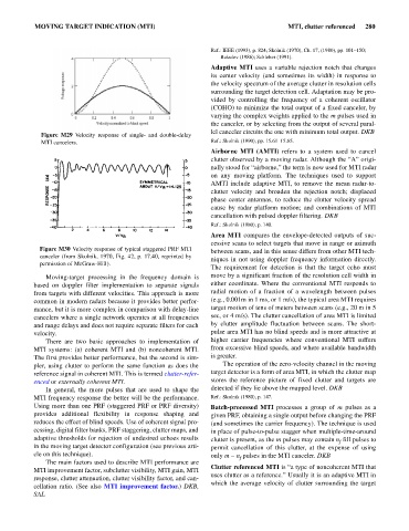
Figure M30 Velocity response of typical staggered PRF MTI
between scans, and in this sense differs from other MTI tech-
canceler (from Skolnik, 1970, Fig. 42, p. 17.40, reprinted by
niques in not using doppler frequency information directly.
permission of McGraw-Hill).
The requirement for detection is that the target echo must
Moving-target processing in the frequency domain is move by a significant fraction of the resolution cell width in
based on doppler filter implementation to separate signals either coordinate. Where the conventional MTI responds to
from targets with different velocities. This approach is more radial motion of a fraction of a wavelength between pulses
common in modern radars because it provides better perfor- (e.g., 0.001m in 1 ms, or 1 m/s), the typical area MTI requires
mance, but it is more complex in comparison with delay-line target motion of tens of meters between scans (e.g., 20 m in 5
cancelers where a single network operates at all frequencies sec, or 4 m/s). The clutter cancellation of area MTI is limited
and range delays and does not require separate filters for each by clutter amplitude fluctuation between scans. The short-
velocity. pulse area MTI has no blind speeds and is more attractive at
There are two basic approaches to implementation of higher carrier frequencies where conventional MTI suffers
MTI systems: (a) coherent MTI and (b) noncoherent MTI. from excessive blind speeds, and where available bandwidth
The first provides better performance, but the second is sim- is greater.
pler, using clutter to perform the same function as does the The operation of the zero-velocity channel in the moving
reference signal in coherent MTI. This is termed clutter-refer- target detector is a form of area MTI, in which the clutter map
enced or externally coherent MTI. stores the reference picture of fixed clutter and targets are
In general, the more pulses that are used to shape the detected if they lie above the mapped level. DKB
MTI frequency response the better will be the performance. Ref.: Skolnik (1980), p. 147.
Using more than one PRF (staggered PRF or PRF diversity) Batch-processed MTI processes a group of m pulses as a
provides additional flexibility in response shaping and given PRF, obtaining a single output before changing the PRF
reduces the effect of blind speeds. Use of coherent signal pro- (and sometimes the carrier frequency). The technique is used
cessing, digital filter banks, PRF staggering, clutter maps, and in place of pulse-to-pulse stagger when multiple-time-around
adaptive thresholds for rejection of undesired echoes results clutter is present, as the m pulses may contain n fill pulses to
f
in the moving target detector configuration (see previous arti- permit cancellation of this clutter, at the expense of using
cle on this technique). only m - n pulses in the MTI canceler. DKB
f
The main factors used to describe MTI performance are
Clutter referenced MTI is “a type of noncoherent MTI that
MTI improvement factor, subclutter visibility, MTI gain, MTI
uses clutter as a reference.” Usually it is an adaptive MTI in
response, clutter attenuation, clutter visibility factor, and can-
which the average velocity of clutter surrounding the target
cellation ratio. (See also MTI improvement factor.) DKB,
SAL