
Page 294 - Radar Technology Encyclopedia
P. 294
MULTIVIBRATOR navigation, range-finding 284
There is big variety of waiting multivibrators block diagrams. difference-range-finding methods.
The circuit with an emitter coupling and voltage versus time Ref.: Smith (1978); Yarlykov (1985); Sonnenberg (1978).
diagrams for it are shown in Fig. 1. AIL
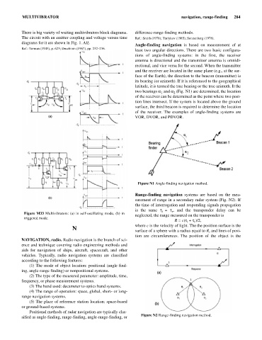
Angle-finding navigation is based on measurement of at
Ref.: Terman (1945), p. 625; Druzhinin (1967), pp. 232–236.
least two angular directions. There are two basic configura-
tions of angle-finding systems: in the first, the receiver
antenna is directional and the transmitter antenna is omnidi-
rectional, and vice versa for the second. When the transmitter
and the receiver are located in the same plane (e.g., at the sur-
face of the Earth), the direction to the beacon (transmitter) is
its bearing (or azimuth). If it is referenced to the geographical
latitude, it is termed the true bearing or the true azimuth. It the
two bearings a and a (Fig. N1) are determined, the location
1
2
of the receiver can be determined as the point where two posi-
tion lines intersect. If the system is located above the ground
surface, the third beacon is required to determine the location
of the receiver. The examples of angle-finding systems are
VOR, DVOR, and PDVOR.
Figure N1 Angle-finding navigation method.
Range-finding navigation systems are based on the mea-
surement of range in a secondary radar system (Fig. N2). If
the time of interrogation and responding signals propagation
is the same t = t, and the transponder delay can be
r
i
Figure M33 Multivibrators: (a) in self-oscillating mode, (b) in
neglected, the range measured on the transponder is
triggered mode.
R = c(t+ t)/2,
i r
where c is the velocity of light. The the position surface is the
N
surface of a sphere with a radius equal to R, and lines of posi-
tion are circumferences. The position of the object is the
NAVIGATION, radio. Radio navigation is the branch of sci-
ence and technique covering radio engineering methods and
aids for navigation of ships, aircraft, spacecraft, and other
vehicles. Typically, radio navigation systems are classified
according to the following features:
(1) The mode of object location: positional (angle find-
ing, angle-range finding) or nonpositional systems.
(2) The type of the measured parameter: amplitude, time,
frequency, or phase measurement systems.
(3) The band used: decameter to optics band systems.
(4) The range of operation: space, global, short- or long-
range navigation systems.
(5) The place of reference station location: space-based
or ground-based systems.
Positional methods of radar navigation are typically clas-
Figure N2 Range-finding navigation method.
sified as angle-finding, range-finding, angle-range-finding, or