
Page 288 - Radar Technology Encyclopedia
P. 288
monopulse, phase-phase MOVING-TARGET DETECTOR (MTD) 278
The phase difference is the receiving channel output have equal amplitude and the
difference signal equals zero.
Df = 2pDR/l = 2pL/l sinq,
The difference signal is used to control the beam position
where l is the wavelength. This provides the capability to during the tracking process. The sum signal is used both as a
define angle q relative to the measured magnitude of the reference signal and for target acquisition and measurement
phase shifts of signals reflected from a target. of its range and velocity. The direction finding characteristic
The direction-finding characteristic is is
–
2
1
2 æ 2pL ö S q() K mq cos= pd ( f f )
=
S q() K V sin ---------- sin q
pd lim è l ø
where K is the phase detector transmission factor, m is the
pd
slope of the difference pattern over its operating region, and
f , f are the phase shifts in the channels. An advantage of
2
1
such a direction finding system is the lax requirement for
match of receiving channel responses, which explains its
wide use in modern monopulse systems. AIL
Ref.: Sherman 91984), Ch. 5; Leonov (1986), p. 78.
Figure M24 Phase-phase monopulse system: (a) elementary
patterns, (b) signal paths, and (c) block diagram (after Leonov,
Figure M25 Sum-and-difference monopulse system: (a) block
1986, Figs. 1.1 and 4.2, p. 68).
diagram, (b) elementary antenna patterns, (c) sum and differ-
ence patterns (after Leonov, 1986, Fig. 4.3, p. 70).
where K is the phase detector transmission factor, and V lim
pd
is the limiting threshold relative to amplitude of signals at
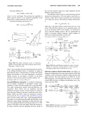
MOVING-TARGET DETECTOR (MTD). The MTD is an
phase detector input. A shortcoming of a system with a phase
enhanced configuration of moving-target indicator (MTI) that
angular discriminator is the great dependence of direction
combines a series of features to improve clutter rejection and
finding accuracy on the degree of identity of the phase
target detection. The main features in an MTD are (a) the
response of the receiving channels and their stability. AIL
MTI precanceler, (b) the doppler filter bank, (c) use of burst-
Ref.:Sherman (1984), Ch. 5; Leonov (1984), p. 67.
to-burst PRF diversity, (d) adaptive thresholding, and (e) the
Sum-and-difference monopulse is a method of determina- clutter map (Fig. M26).
tion of angular coordinates in monopulse systems using
amplitude or phase direction-finding and a sum-and-differ-
ence angle measurement method (sum-and-difference dis-
criminator). Most widely used are amplitude sum-and-
difference monopulse systems, a block diagram of which for
target direction finding in one plane is depicted in Fig. M25a.
Figures M25b and M25c depict the elementary patterns,
F (q) and F (q), the sum pattern S(q), and difference pattern
2
1
s
i
D(q), of such a system, with + and - gns designating the rel-
ative phase. It is evident from this figure that the phase of the
difference signal changes depending on target direction rela-
tive to the equisignal direction and may be either at 0 or 180°
relative to the phase of the sum signal. When the direction to Figure M26 Block diagram of typical moving target detector
the target coincides with the equisignal direction, signals in (from Schleher, 1991, Fig. 1.29, p. 39).