
Page 285 - Radar Technology Encyclopedia
P. 285
275 modulator MONOPULSE
Table M4
Comparison of Modulators
Crowbar
Flexibility Pulse-length capability
required Modul-
Pulse ator
Modulator Mixed flatness voltage
Duty cycle pulse Long Short Load Switch level
arc arc
lengths
Line Thyratron/ Limited by No Large PFN Good Ripples No Medium/
type SCR charging low
circuit
Magnetic Limited by No Large Cs and Good Ripples No Low
reset and PFN
charging time
Hybrid SCR magnetic Limited by No Excellent; large Good Ripples No Low
modulator reset and capacitor bank
charging time
Active Series No limit Yes Large coupling Good Good Maybe Yes High
switch switch capacitor
Capacitor- Limited Yes Difficult; XF Good Good Maybe Yes High
coupled gets big; large
capacitor bank
Trans- Limited Yes Excellent; large Good Fair Maybe Yes Medium/
former- capacitor bank high
coupled
Mod-anode No limit Yes Excellent; large OK, but Excellent Yes Yes High
capacitor bank efficiency
low
Grid No limit Yes Excellent Excellent Yes - Low
(from Skolnik, 1990, Table 4.3, p. 4.34, reprinted by permission of McGraw-Hill)
MONOPULSE is “a radar technique in which information having a single-valued relation to the angle of arrival of the
concerning the angular location of a source or target is signals. There are three basic types of techniques for angle
obtained by comparison of signals received in two or more sensors: amplitude comparison, phase-comparison, and com-
simultaneous antenna beams, as distinguished from tech- bination (Fig. M17).
niques such as lobe switching or conical scanning in which In the amplitude-comparison angle-sensing technique,
beams are generated sequentially. The simultaneity of the two identical overlapping beams are formed with an offset of
beams makes it possible to obtain a two-dimensional angle ±q from the equisignal direction or null axis (the axis along
0
estimate from a single pulse (hence the term monopulse), which the amplitudes of two patterns are equal). When the
although multiple pulses are usually employed to improve the target is offset by an angle q om the axis, the signal received
r
f
accuracy of the estimate or to provide doppler resolution.” through the lower beam has a greater amplitude then the sig-
The generic block diagram of a monopulse system is shown nal received through the higher beam. The amplitude of this
in Fig. M16.
Angle Comparator Angle
sensor (converter) discriminator
Figure M16 Block diagram of monopulse system (after
Leonov, 1986, Fig. 1.2, p. 8).
It consists of an angle sensor that forms signals contain-
ing the target angle information, a comparator (or converter)
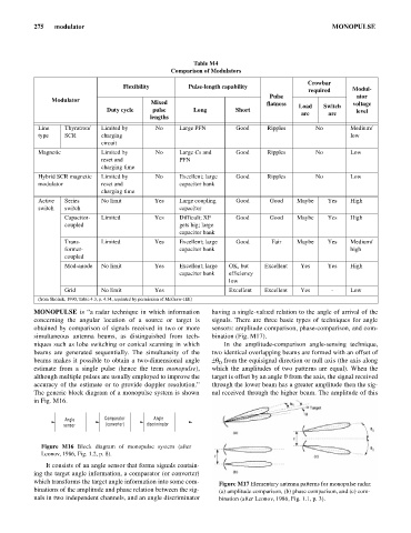
which transforms the target angle information into some com- Figure M17 Elementary antenna patterns for monopulse radar:
binations of the amplitude and phase relation between the sig- (a) amplitude comparison, (b) phase comparison, and (c) com-
nals in two independent channels, and an angle discriminator bination (after Leonov, 1986, Fig. 1.1, p. 3).