
Page 305 - Radar Technology Encyclopedia
P. 305
295 oscillator, traveling-wave-tube (TWT) oscillator, voltage-controlled (VCO)
be made either over a special channel or through internal Table O2
reflections of the electromagnetic wave at discontinuities of Types of Tube Oscillators
the coil, chiefly at points of the transmission from the spiral
Type of Oscillators Basic Use
waveguide structure to the waveguide or coaxial transmission
klystron local oscillator for radar in cm or mm
line, through which the signal is sent to the device or taken
bands
from it to the load.
Traveling-wave-tube oscillators of the O type with low magnetron power generator for radar in dm, cm,
power are widely used as wideband voltage-controlled oscil- or mm bands
lators (VCOs) and also for local oscillators and RF fre- amplitron (stabilitron) generator for medium- and high-
quency-agility oscillators. Variants of such higher power power radar in dm, cm, or mm
tubes for radar transmitters have not been developed due to bands with high frequency stability
the requirement for precise stabilization of the high voltage backward-wave-tube generators for low- and medium-
and the lack of advantages over tubes of other types. Travel- power radars in cm and mm bands
ing-wave tubes are more widely used in transmitters as ampli- with electronic frequency tuning
fiers of oscillations of the master oscillator. (See traveling-wave-tube wideband generators for medium
AMPLIFER, traveling-wave-tube.) IAM power in cm and mm bands
Ref.: Popov (1980), p. 82; Perevezentsev (1981), p. 165. gyrotron powerful radar oscillators in mm
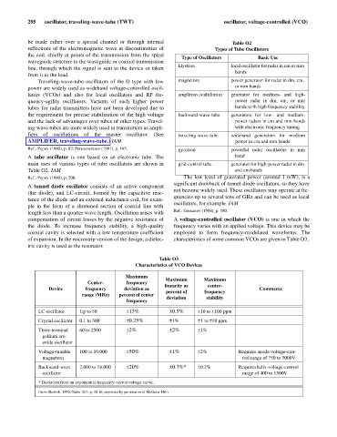
A tube oscillator is one based on an electronic tube. The band
main uses of various types of tube oscillators are shown in grid-control tube generator for high-power radar in dm
Table O2. IAM and cm bands
Ref.: Popov (1980), p. 206. The low level of generated power (around 1 mW), is a
significant drawback of tunnel-diode oscillators, so they have
A tunnel diode oscillator consists of an active component
not become widely used. These oscillators may operate at fre-
(the diode), and LC-circuit, formed by the capacitive reac-
quencies up to several tens of GHz and can be used as local
tance of the diode and an external inductance coil, for exam-
oscillators, for example. IAM
ple in the form of a shortened section of coaxial line with
Ref.: Gassanov (1988), p. 180.
length less than a quarter wave length. Oscillation arises with
compensation of circuit losses by the negative resistance of A voltage-controlled oscillator (VCO) is one in which the
the diode. To increase frequency stability, a high-quality frequency varies with an applied voltage. This device may be
coaxial cavity is selected with a low temperature coefficient employed to form frequency-modulated waveforms. The
of expansion. In the microstrip version of the design, a dielec- characteristics of some common VCOs are given in Table O3.
tric cavity is used as the resonator.
Table O3
Characteristics of VCO Devices
Maximum
Maximum Maximum
Center- frequency
linearity as center-
Device frequency deviation as Comments
percent of frequency
range (MHz) percent of center
deviation stability
frequency
to
ppm
LC oscillator Up to 50 ± 15% ± 0.5% ±10 ±100
Crystal oscillator 0.1 to 300 ± 0.25% ±1% ±1 ±10
ppm
to
Three-terminal 60 to 2500 ± 2% ± 2% ±1%
gallium ars-
enide oscillator
Voltage-tunable 100 to 10,000 ± 50% ± 1% ±2% Requires anode-voltage-con-
magnetron trol range of 750 to 3000V
Backward-wave 2,000 to 18,000 ± 20% ± 0.3%* ±0.2% Requires helix-voltage-control
oscillator range of 400 to 1500V
* Deviation from an exponential frequency-versus-voltage curve.
(from Skolnik, 1990, Table 10.3, p. 10.16, reprinted by permission of McGraw-Hill).