
Page 307 - Radar Technology Encyclopedia
P. 307
297 PATTERN, antenna (radiation) pattern, array (antenna)
actual radiation patterns, but a plot of the voltage pattern where
shows the alternating phase of the principal sidelobes, 180°
( q– q ) q q )
(
–
3
2
and 0°relative to the mainlobe. A more complete character- k = --------------------------------------------
1
–
(
q ) q q )
(
q –
ization of the radiated field requires plots of amplitude and 1 2 1 3
phase separately, as functions of angle. DKB ( q– q ) q q )
(
–
1
3
Ref.: IEEE (1993), p. 1057; Johnson (1984), p. 1.5. k = --------------------------------------------
2
(
(
q –
–
q ) q q )
2 1 2 3
An antenna pattern approximation is a mathematical
–
(
model approximating the actual pattern with some analytical ( q– q ) q q )
2
2
k = --------------------------------------------
3
(
–
expression to be used for analysis or synthesis. The most ( q – q ) q q )
2
3
3
1
common approximations are the Gaussian approximation and DKB, SAL
the (sinx)/x functions, and the pattern of a cosine-illuminated
Ref.: Barton (1969), pp. 254, 280–285; (1991), App. F.
aperture is also used to match a class of practical antennas.
),
The array (antenna) pattern, f (q,f is the product of two
The first is an idealized pattern of an antenna having a smooth arr
factors: the array element pattern, f (q,f), and the array factor,
mainlobe with no sidelobes. The voltage gain pattern is e
f (q,f). The first is the pattern produced when an individual
a
2
q element in the array is excited, while the second expresses the
f q() exp –= 1.3863----- 2
q effect of controlled excitation of all elements of the array.
3
Thus:
where q is the half-power beamwidth. The power gain pat-
3
,
2
=
(
,
×
(
,
tern, G(q) = f (q), has the same form but with the constant f ( qf) f qf)f qf)
e
a
arr
2.7725 in the exponential argument. The Gaussian approxi- The element pattern is relatively broad (resulting, for
mation is used when only the mainlobe of the actual antenna example, from a single dipole), and it is the array factor that
needs to be considered (e.g., in calculation of beamshape loss determines the width and direction of the radiated (or
or spectral spreading of clutter echoes). A true Gaussian pat- received) beam. For a uniformly spaced linear array it can be
tern would require an infinite aperture with Gaussian illumi- shown that, in the single plane q,
nation function, but approximations may be produced by
N 1–
truncating the aperture. For example, truncation at the -9-dB
exp
f q() = å Ax ( ) { j f x ([ ) kndsin+ q ]} (1)
level of illumination produces a pattern with -21-dB side- a n n
lobes. n = 0
The (sinx)/x pattern describes the voltage gain of a uni- where A(x )exp(jfx ) is a complex amplitude-phase distribu-
n
n
formly illuminated linear or rectangular aperture: tion of the illuminating (exciting) field over the aperture (A is
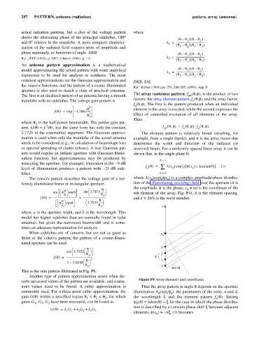
the amplitude, f is the phase, x = nd is the coordinate of the
n
æ w ö æ q ö
sin p---- sin q sin 2.7831----- nth element of the array, Fig. P4), d is the element spacing,
è l ø è q ø
3
f q() -------------------------------------- = ------------------------------------ and k = 2p/l is the wave number.
=
q
æ p---- sin q æ 2.7831----- ö
w ö
è l ø è q ø x
3
where w is the aperture width, and l is the wavelength. This
model has higher sidelobes than are normally found in radar
antennas, but gives the narrowest beamwidth and is some-
times an adequate representation for analysis.
When sidelobes are of concern, but are not as great as x
those of the (sinx)/x pattern, the pattern of a cosine-illumi- n
nated aperture can be used:
3
q ö
æ
cos 3.7352 -----
è q ø 2
3
f q() ------------------------------------------ d 1
=
2
q
æ
1 – 5.6544 ----- ö
è q ø
3 0
ndsinq
This is the sum pattern illustrated in Fig. P6.
Another type of pattern approximation arises when dis-
crete measured values of the pattern are available, and contin- Figure P4 Array elements and coordinates.
uous values need to be found. A cubic approximation is Thus the array pattern in angle q depends on the aperture
commonly used. For a three-point cubic approximation, the illumination A exp(jf ), the parameters of the array, n and d,
n
n
gain G(q) within a specified region q < q < q , for which the wavelength l and the element pattern f (q). Setting
1
3
2
e
gains G , G , G have been measured, can be found as y (q)= kdsin(q) - x for the case in which the phase distribu-
3
1
2
0
tion is described by a constant phase shift x between adjacent
G q() k G += 1 1 k G + k G 3
2
3
2
elements, f(x ) = -nx, (1) becomes
n