
Page 309 - Radar Technology Encyclopedia
P. 309
299 pattern, omnidirectional PERMEABILITY
An omnidirectional pattern is one with constant value of way that the target will first be traversed by the vertical beam
gain over a sphere, or in a single angular coordinate (e.g., azi- and then by the inclined beam. Target altitude is given by
muth). SAL Rsin q
h = --------------------------
Ref.: Johnson (1984), p. 1.13. 2
1 + sin q
pattern-propagation factor (see PROPAGATION).
where R is the slant range to the target and q is the antenna
The spillover pattern is a set of sidelobes, typically at angles rotation angle between the center of the target blips in the
90° to 120°from the mainlobe of a reflector antenna, that channels of the vertical and inclined beams. AIL
result from horn radiation that misses the periphery of the Ref.: Skolnik (1970), p. 22.3.
reflector and radiates directly into space. DKB
PERFORMANCE, radar. Radar performance is the set of
The sum pattern of a monopulse antenna is the pattern of the
characteristics defining the quality of radar operation. In Rus-
on-axis beam formed, in a simple four-horn feed, by sum-
sian literature, radar performance figures are usually referred
ming all four horns in-phase. In more complex feed systems,
to as tactical-technical characteristics. Tactical characteris-
the sum beam is formed by coupling the horns or array ele-
tics describe top-level performance and typically include (1)
ments to produce an illumination function with even symme-
maximum and minimum operational ranges (detection range,
try and with a shape designed to create the highest possible
for search radar); (2) coverage angles; (3) resolution; (4) mea-
gain at the beam axis, for given sidelobe levels. (See differ-
surement accuracy (or errors); (5) throughput capacity; (6)
ence pattern; MONOPULSE.) DKB
interference immunity; and (7) availability. The technical
Ref.: Barton (1988), pp. 198–205, 399–408. characteristics include lower level parameters: operating fre-
The two-way pattern of an antenna is the product of the quency, transmitter power, pulse repetition frequency,
transmit pattern and the receive pattern. In general, for trans- antenna gain (directivity), receiver sensitivity, and so forth.
mit beamwidth q and receive beamwidth q at the -3-dB The radar performance can be evaluated through a combina-
3t
3r
points, the beamwidth of the two-way pattern at the -6-dB tion of analysis, simulation, and subsystem and system test-
level is given by ing. The flow of the performance evaluation in the process of
design and testing is shown in Fig P8. SAL
2q q
3t 3r
q = ------------------------- Ref.: Leonov (1988), p. 23; Barton (1991) p. 13.1.
6 2 2
q + q
3t 3r
which can be considered an effective one-way, -3-dB beam-
width for the pattern pair. DKB
Ref.: Barton (1993), p. 88.
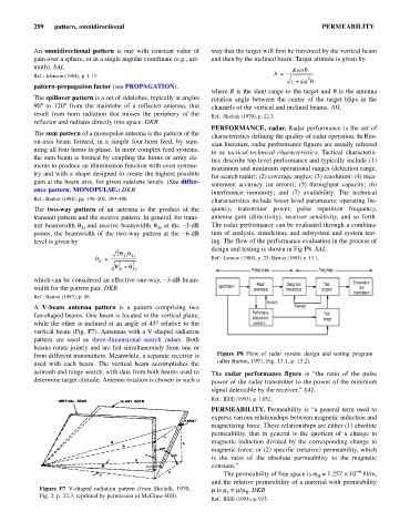
A V-beam antenna pattern is a pattern comprising two
fan-shaped beams. One beam is located in the vertical plane,
while the other is inclined at an angle of 45°relative to the
vertical beam (Fig. P7). Antennas with a V-shaped radiation
pattern are used as three-dimensional search radars. Both
beams rotate jointly and are fed simultaneously from one or
from different transmitters. Meanwhile, a separate receiver is Figure P8 Flow of radar system design and testing program
(after Barton, 1991, Fig. 13.1, p. 13.2).
used with each beam. The vertical beam accomplishes the
azimuth and range search, with data from both beams used to The radar performance figure is “the ratio of the pulse
determine target altitude. Antenna rotation is chosen in such a power of the radar transmitter to the power of the minimum
signal detectable by the receiver.” SAL
Ref.: IEEE (1993), p. 1,052.
PERMEABILITY. Permeability is “a general term used to
express various relationships between magnetic induction and
magnetizing force. These relationships are either (1) absolute
permeability, that in general is the quotient of a change in
magnetic induction divided by the corresponding change in
magnetic force; or (2) specific (relative) permeability, which
is the ratio of the absolute permeability to the magnetic
constant.”
-6
The permeability of free space is m = 1.257 ´ 10 H/m,
0
and the relative permeability of a material with permeability
Figure P7 V-shaped radiation pattern (from Skolnik, 1970, m is m = m/m . DKB
r
0
Fig. 2, p. 22.3, reprinted by permission of McGraw-Hill).
Ref.: IEEE (1993), p. 935.