
Page 313 - Radar Technology Encyclopedia
P. 313
303 phase shifter, multielement phase shifter, switched-line
A multielement phase shifter is a discrete phase shifter pro-
viding phase variation in a specified range with the specified
Ac
discrete Df. tually, it is multidigit phase shifter, each digit
of which can be in either of two states: the phase shift of the
ith digit Df is present or absent. The number of digits n is
i
as
defined via specified Df
n = 1 + log (p/Df)
2
Multielement phase shifters are realized through diode
phase shifters, field-effect transistor phase shifters, and other
electrical phase shifters. They are widely used in phased
arrays (number of digits is typically 5 or 6). IAM
Ref.: Voskresenskiy (1981), p. 369.
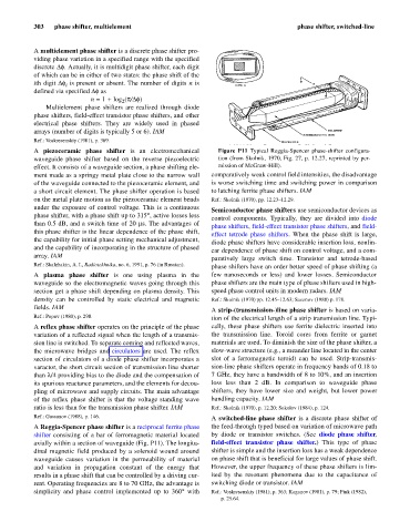
A piezoceramic phase shifter is an electromechanical Figure P11 Typical Reggia-Spencer phase-shifter configura-
waveguide phase shifter based on the reverse piezoelectric tion (from Skolnik, 1970, Fig. 27, p. 12.27, reprinted by per-
effect. It consists of a waveguide section, a phase shifting ele- mission of McGraw-Hill).
ment made as a springy metal plate close to the narrow wall comparatively weak control field intensities, the disadvantage
of the waveguide connected to the piezoceramic element, and is worse switching time and switching power in comparison
a short circuit element. The phase shifter operation is based to latching ferrite phase shifters. IAM
on the metal plate motion as the piezoceramic element bends Ref.: Skolnik (1970), pp. 12.23–12.29.
under the exposure of control voltage. This is a continuous
Semiconductor phase shifters use semiconductor devices as
,
phase shifter, with a phase shift up to 315° active losses less
control components. Typically, they are divided into diode
than 0.5 dB, and a switch time of 20 ms. The advantages of
phase shifters, field-effect transistor phase shifters, and field-
this phase shifter is the linear dependence of the phase shift,
effect tetrode phase shifters. When the phase shift is large,
the capability for initial phase setting mechanical adjustment,
diode phase shifters have considerable insertion loss, nonlin-
and the capability of incorporating in the structure of phased
ear dependence of phase shift on control voltage, and a com-
array. IAM
paratively large switch time. Transistor and tetrode-based
Ref.: Skalzhakin, A. I., Radiotekhnika, no. 6, 1991, p. 76 (in Russian).
phase shifters have an order better speed of phase shifting (a
A plasma phase shifter is one using plasma in the few nanoseconds or less) and lower losses. Semiconductor
waveguide so the electromagnetic waves going through this phase shifters are the main type of phase shifters used in high-
section get a phase shift depending on plasma density. This speed phase control units in modern radars. IAM
density can be controlled by static electrical and magnetic Ref.: Skolnik (1970) pp. 12.45–12.63; Sazonov (1988) p. 178.
fields. IAM
A strip-(transmission-)line phase shifter is based on varia-
Ref.: Popov (1980), p. 290.
tion of the electrical length of a strip transmission line. Typi-
A reflex phase shifter operates on the principle of the phase cally, these phase shifters use ferrite dielectric inserted into
variation of a reflected signal when the length of a transmis- the transmission line. Toroid cores from ferrite or garnet
sion line is switched. To separate coming and reflected waves, materials are used. To diminish the size of the phase shifter, a
the microwave bridges and circulators are used. The reflex slow-wave structure (e.g., a meander line located in the center
section of circulators of a diode phase shifter incorporates a slot of a ferromagnetic toroid) can be used. Strip-transmis-
varactor, the short circuit section of transmission line shorter sion-line phase shifters operate in frequency bands of 0.18 to
than l/4 providing bias to the diode and the compensation of 7 GHz, they have a bandwidth of 8 to 10%, and an insertion
its spurious reactance parameters, and the elements for decou- loss less than 2 dB. In comparison to waveguide phase
pling of microwave and supply circuits. The main advantage shifters, they have lower size and weight, but lower power
of the reflex phase shifter is that the voltage standing wave handling capacity. IAM
ratio is less than for the transmission phase shifter. IAM Ref.: Skolnik (1970), p. 12.20; Sokolov (1984), p. 124.
Ref.: Gassanov (1988), p. 146. A switched-line phase shifter is a discrete phase shifter of
A Reggia-Spencer phase shifter is a reciprocal ferrite phase the feed-through typed based on variation of microwave path
shifter consisting of a bar of ferromagnetic material located by diode or transistor switches. (See diode phase shifter,
axially within a section of waveguide (Fig. P11). The longitu- field-effect transistor phase shifter.) This type of phase
dinal magnetic field produced by a solenoid wound around shifter is simple and the insertion loss has a weak dependence
waveguide causes variation in the permeability of material on phase shift that is beneficial for large values of phase shift.
and variation in propagation constant of the energy that However, the upper frequency of these phase shifters is lim-
results in a phase shift that can be controlled by a driving cur- ited by the resonant phenomena due to the capacitance of
rent. Operating frequencies are 8 to 70 GHz, the advantage is switching diode or transistor. IAM
simplicity and phase control implemented up to 360° with Ref.: Voskresenskiy (1981), p. 363; Kaganov (1981), p. 79; Fink (1982),
p. 25.64.