
Page 315 - Radar Technology Encyclopedia
P. 315
305 POLARIZATION polarization efficiency
niques; those requiring dual-polarization or polarization agil- angle of 71° for the right-hand component and 289° for the
ity and utilizing only part of scattering matrix content are left-hand component. SAL
called vector techniques; and under the assumption of a con- Ref.: Johnson (1984), p. 23.6.
stant polarization state the techniques are called scalar. The
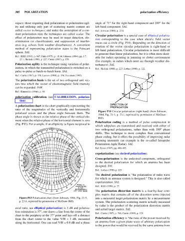
Circular polarization is a special case of elliptical polariza-
effect of polarization may be used in target detection, dis-
tion corresponding to the case when electric field vector
crimination (or classification), and suppression of interfer-
traces out a circle (Fig. P14). Depending on the direction of
ence (e.g. echoes from weather disturbances). A convenient
rotation of the vector circular polarization is right-hand or
method of representing polarization states is the Poincaré
left-hand polarization. Circular polarization is more difficult
sphere. SAL
to generate than linear polarization, but it is often more desir-
Ref.: IEEE (1993), p. 967; Fink (1975), p. 18.14; Johnson (1984), pp. 1.7, able for radars operating in jamming or clutter environment
23.1; Skolnik (1980), p. 227; Currie (1987), p. 158.
(for example, in radars which must see through weather dis-
Polarization agility is the technique using variation of polar- turbances). SAL
ization, in which the transmitted polarization is switched on a Ref.: Skolnik (1980), p. 227; Lothes (1990), p. 122.
pulse-to-pulse or batch-to-batch basis. SAL
Ref.: Currie (1987), p. 158; Leonov (1988), p. 156; Stutzman (1992).
The polarization basis is the set of two orthogonal unit vec-
tors into which the vector of electromagnetic field intensity
can be expanded. IAM
Ref.: Kanareikin (1966), p. 30.
polarization calibration (see CALIBRATION, polariza-
tion).
A polarization chart is the chart graphically representing the
ratio of the magnitudes of the vertically and horizontally
Figure P14 Circular polarization (right-hand) (from Johnson,
polarized waves and the phase angle between them. The
1984, Fig. 23-1, p. 23.1, reprinted by permission of McGraw-
phase angle is shown as the relative phase of the vertical ele-
Hill).
ment when the relative phase of the horizontal element is zero
Polarization coding is a method of pulse compression in
(Fig. P13). For example, if an ellipticity (a figure reciprocal to
which subpulses are transmitted and received with either of
two orthogonal polarizations, rather than with 180° phase
shifts. This technique is more complex than conventional
phase coding, but it offers the possibility of improving radar
jamming immunity (an example is the so-called Intrapulse
Polarization Agile Radar). SAL
Ref. Eaves (1987), pp. 490–492.
copolarization (see desired polarization).
Cross-polarization is the undesired component, orthogonal
to the desired polarization for which an antenna has been
designed. SAL
Ref.: Lothes (1990), p. 123.
The desired polarization is “the polarization of radio wave
for which an antenna system is designed.” This is also called
copolarization. SAL
Ref.: IEEE (1990), p. 23.
The polarization distortion matrix is a four-by-four com-
plex matrix that contains all of the distortion terms injected
Figure P13 Polarization chart (from Johnson, 1984, Fig. 23-5, into a measured target polarization matrix by a measurement
p. 23-6, reprinted by permission of McGraw-Hill). system. The polarization scattering matrix actually measured
by radar is the product of the polarization distortion matrix
axial ratio, see elliptical polarization) is 3 dB and polariza- and actual target matrix. SAL
tion orientation is 37° one draws a line from the center of the
,
Ref.: Currie (1987), p. 768; Currie (1989), p. 129.
chart to the periphery at the 37° point and lays off a distance
from the chart center to the value V/H = 3 dB, measured Polarization efficiency is “the ratio of the power received by
along the horizontal. One can read V/H = 0.8 dB and a phase an antenna from a given plane wave of arbitrary polarization
to the power that would be received by the same antenna from