
Page 316 - Radar Technology Encyclopedia
P. 316
polarization efficiency polarization parameter measurement 306
a plane wave of the same power density and direction of
propagation, whose state of polarization has been adjusted for
Table P2
a maximum received power.” SAL
Reflected Polarizations for Various Reflectors
Ref.: IEEE (1993), p. 967.
The polarization ellipse is an elliptical path along which the Illuminated Polarization
electrical field vector of a polarized wave moves in the plane
Reflector Circular
orthogonal to the wave normal. SAL
V H +45° - 45°
Ref.: Johnson (1984), p. 1.7.
RH LH
Elliptical polarization is the general case in which the elec-
Flat plate V H +45° - 45° LH RH
tric field vector traces out an ellipse (Fig. P15). Elliptical
polarization is characterized by an axial ratio, which is the Sphere V H +45° - 45° LH RH
ratio of the major axis to the minor axis of the polarization
Trihedral V H +45° - 45° LH RH
ellipse (sometimes the term ellipticity, which is reciprocal to
axial ratio is used), the tilt of the axis of the polarization Dihedral (V) V H - 45° +45° RH LH
ellipse, polarization orientation (the direction in which the Dihedral H V +45° - 45° RH LH
major axis lies), and the direction of rotation of the E-vector. (45° )
Linear and circular polarizations are special cases of elliptical
Dihedral +45° - 45° V H RH LH
polarization. SAL
(22.5° )
(after Currie, 1984, Table 4-1, p. 128)
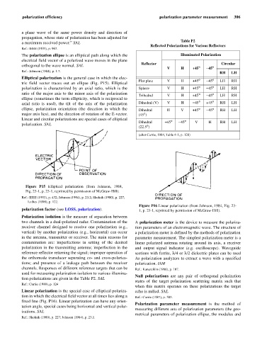
Figure P15 Elliptical polarization (from Johnson, 1984,
Fig. 23-1, p. 23-1, reprinted by permission of McGraw-Hill).
Ref.: IEEE (1993), p. 432; Johnson (1984), p. 23.2; Skolnik (1980), p. 227;
Lothes (1990), p. 122.
Figure P16 Linear polarization (from Johnson, 1984, Fig. 23-
polarization factor (see LOSS, polarization). 1, p. 23-1, reprinted by permission of McGraw-Hill).
Polarization isolation is the measure of separation between
two channels in a dual-polarized radar. Contamination of the A polarization meter is the device to measure the polariza-
receiver channel designed to receive one polarization (e.g., tion parameters of an electromagnetic wave. The structure of
vertical) by another polarization (e.g., horizontal) can occur a polarization meter is defined by the methods of polarization
in the antenna, transmitter or receiver. The main reasons for parameter measurement. The simplest polarization meter is a
contamination are: imperfections in setting of the desired linear polarized antenna rotating around its axis, a receiver
polarization in the transmitting antenna; imperfection in the and output signal indicator (e.g. oscilloscope). Waveguide
reference reflector returning the signal; improper operation of sections with ferrite, l/4 l/2electric plates can be used
d
i
or
the orthomode transducer separating co- and cross-polariza- As polarization analyzers to extract a wave with a specified
tions; and presence of a leakage path between the receiver polarization. IAM
channels. Responses of different reference targets that can be Ref.: Kanareikin (1966), p. 107.
used for measuring polarization isolation to various illumina-
Null polarizations are any pair of orthogonal polarization
tion polarizations are given in the Table P2. SAL
states of the target polarization scattering matrix such that
Ref.: Currie (1989), p. 124
when this matrix operates on these polarizations the target
Linear polarization is the special case of elliptical polariza- echo is nulled. SAL
tion in which the electrical field vector at all times lies along a Ref.: Currie (1987), p. 303.
fixed line (Fig. P16). Linear polarization can have any orien-
Polarization parameter measurement is the method of
tation angle, special cases being horizontal and vertical polar-
measuring different sets of polarization parameters (the geo-
izations. SAL
metrical parameters of polarization ellipse, the modulus and
Ref.: Skolnik (1980), p. 227; Johnson (1984), p. 23.1.