
Page 321 - Radar Technology Encyclopedia
P. 321
311 propagation, ionospheric propagation over the earth
duced. When the wavelength is 5 to 10m or less, the iono- For radar applications, the most important considerations
sphere serves as a reflecting medium that makes it possible to are wave propagation in the atmosphere (see propagation in
implement over-the-horizon detection of targets. (See the troposphere, ionospheric propagation) and propagation
RADAR, over-the-horizon.) The main effects of the iono- in a ferrite medium whose properties are used in different
sphere are inversely proportional to the square of the fre- microwave devices: phase shifters, attenuators, and so forth.
quency. For a frequency of 300 MHz, the maximum variation Typically, the propagation medium is characterized by the
in range is about 300m, and in elevation (due to refraction) losses it inserts in the propagating wave, that can lie from
0.5 mrad, that is much less than for propagation in the tropo- fractions of a decibel to hundreds of decibels (e.g., for inter-
sphere. The maximum polarization rotation for quasilongitu- planetary medium in radar astronomy). IAM
dal propagation (Faraday rotation effect) is about 13 rad (the Ref.: Nikol’skiy (1969), p. 35.
variation in polarization structure due to quasitransversal
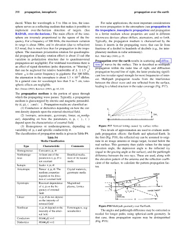
Propagation over the earth results in scattering and diffrac-
propagation are negligible). For wideband waveforms there is
tion of waves by the surface. This is described as multipath
an effect of signal distortion (pulse dispersion, or “blurring”) propagation within the radar line of sight, and diffraction
2
f
that can be neglected for relative bandwidths of Df £ 1.5 propagation beyond line of sight, the latter producing signifi-
0
where f is the carrier frequency in gigahertz. For 300 MHz, cant loss in radar signal strength for most frequencies of inter-
0
- 5
the attenuation in the ionosphere is about 1.3 ´ 10 dB/km.
est. Multipath propagation results from the interference
In a general case for wavelength less than 5 to 7 cm, iono-
between the direct wave and one reflected from the surface,
spheric effects are negligible. IAM
leading to a lobed structure in the radar coverage (Fig. P17).
Ref.: Davies (1965); Kravtsov (1983), pp. 65, 110.
The propagation medium is the portion of space through
which the propagating wave passes. Typically, a propagation
medium is characterized by electric and magnetic permeabil-
a
n ()
ity (e, m), d M . Propagation media are classified as:
P
()
(1) Conductors or dielectrics depending on how the cur- h
rent density depends upon the external electrical field. r
(2) Isotropic, anisotropic, gyrotropic, linear, or nonlin- l /4h r
,
ear), depending on how the parameters, e, m, ()
() P
M
depend upon the characteristics of external field.
(3) Homogenous or nonhomogeneous, depending on Figure P17 Vertical lobing caused by surface reflec-
,
variability of me and specific conductivity s. Two levels of approximation are used to evaluate multi-
The classification of propagation media is given in Table P4. path propagation effects: flat-Earth and spherical-Earth. In
Table P4 the first (Fig. P18), the reflected ray can be assumed to origi-
Media Classification nate in an image antenna or image target, located below the
real surface. This geometry then yields values for the target
Type Characteristic Comments
elevation angle, the depression angle to the reflected ray
Homogeneous Constant e , m , s
(equal to the grazing angle at the surface), and the pathlength
Nonhomoge- At least one of the Stratified media, difference between the two rays. These are used, along with
nous parameters e , m , s is most of the natural
the elevation pattern of the antenna and the reflection coeffi-
not constant media
cient of the surface, to calculate the pattern-propagation fac-
Isotopic Scalar e , m , s
tor.
Anisotropic Tensor e , m , s : The Crystal materials,
medium properties gyrotropic media
depend on the direc-
tion of external field
Gyrotropic Resonant dependence Magnetized
of e , m on the fre- plasma, ferrites
quency of external
field
Linear e , m , s do not depend
on the intensity of
external field
Figure P18 Multipath geometry over flat Earth.
Nonlinear e , m , s depend on the Ferromagnets, seg-
intensity of the exter- netoelectrics The angles and pathlength difference may be corrected as
nal field needed for longer paths, using spherical-earth geometry. In
Conductors s /(wee) >>1 that case, three propagation regions may be distinguished
0
(Fig. P19):
Dielectrics s /(wee) <<1
0