
Page 325 - Radar Technology Encyclopedia
P. 325
315 pulse, uncoded [simple] pulse compression, analog
frequency, which would result in decreasing the unambiguous
range; since the long pulse is used on transmit, increased dop-
pler resolution is possible; when coded waveforms are used, a
radar is less vulnerable to interference. The cost to be paid for
these advantages is greater complexity relative to simple
pulse transmissions, complexity of pulse-compression wave-
form generation and processing, all increasing the cost of the
radar system. SAL
Ref.: IEEE (1990), p. 23; Barton (1988), pp. 220–230; Barton (1991),
pp. 7.2–7.31; Skolnik (1980), pp. 420–434; Skolnik (1990), pp. 10.1–
Figure P23 Simple rectangular pulse (from Bogush, 1989, 10.39; Brookner (1988), pp. 143–148; Lewis (1986), pp. 7–116; Leonov
Fig. 3.54, p. 193). (1988), p. 62.
inexpensive radars when signal generation and signal pro-
cessing cost must be minimized, and when the requirements
to have sufficient energy for detection and tolerable range
accuracy can be met simultaneously. Sometimes simple
pulses are called uncoded pulses or Class A waveforms. SAL
Ref.: Bogush (1989), p. 192.
PULSE COMPRESSION is “the processing of a wideband,
coded signal pulse, of initially long time duration and low-
range resolution, to result in an output pulse of time duration
corresponding to the reciprocal of the bandwidth and, hence,
higher range resolution, and with approximately the same
pulse energy.” In principle, the process of pulse compression
is the by-effect when the signal with intrapulse modulation is
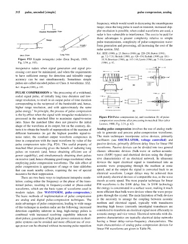
Figure P24 Pulse compression (a), and resolution (b) of pulse-
processed in the matched filter to maximize signal-to-noise
compression waveforms after processing in matched filter (after
ratio. Since the matched filter does not preserve the initial
Leonov, 1988, Fig. 2.21, p. 62).
shape of the waveform at its output, but on the contrary, dis-
torts it to obtain the benefit of superposition of the maxima of Analog pulse compression involves the use of analog meth-
different harmonics (to get the highest possible signal-to- ods to generate and process pulse-compression waveforms.
noise ratio), the resultant output waveform compresses in The main techniques incorporate active devices, primarily
time in comparison with the input waveform by value of the oscillators (see OSCILLATOR, voltage controlled) and
pulse compression ratio (Fig. P24). This useful property of passive devices, primarily different delay lines for linear FM
matched filter processing gives the benefit of radiating long waveforms. Passive devices can be divided into two general
pulses on transmit (and, hence obtaining efficient use of classes: ultrasonic devices (bulk-wave or surface-acoustic-
power capability), and simultaneously obtaining short pulses wave (SAW) types) and electrical devices using the disper-
on receive (and, hence obtaining good range resolution) when sive characteristics of an electrical network. In ultrasonic
employing pulse-compression waveforms. The side effect of devices the input electrical signal is transformed into an
pulse compression is appearance of range or time sidelobes acoustic wave propagating through the medium at sonic
that can mask nearby echoes, requiring the use of special speed, and at the output the signal is converted back to an
measures for their suppression. electrical waveform. Longer delays may be achieved than
There are two basic ways to implement intrapulse modu- with purely electrical devices of comparable size, as the wave
lation: coding either the frequency or the phase of the trans- travels at sonic speed. The most popular technique for linear
mitted pulses, resulting in frequency-coded or phase-coded FM waveforms is the SAW delay line. In SAW technology
waveforms, which are the basic types of waveforms used in the energy is concentrated in a surface wave, making it much
modern radars. (See WAVEFORM, pulse-compression.) more efficient than bulk-wave devices where the wave propa-
The basic methods of implementation of pulse compression gates through the crystal. The main limitation of bulk devices
are analog and digital pulse-compression techniques. The is the necessity to arrange the coupling between acoustic
main advantages of pulse compression, leading to wide usage medium and electrical signal, typically with transducers
of this technique in modern radar are the following: increased inserting high losses (currently interdigital transducers are
detection capability inherent in long, high-energy pulses is considered to transform an electrical signal most efficiently to
combined with increased resolving capability inherent in acoustic energy and vice versa). Electrical networks with dis-
short pulses; generation of high peak power common in short- persive characteristics are typically electrical delay networks
pulse systems can be avoided and more efficient use of aver- having a linear delay-versus-frequency characteristics. The
age power can be obtained without increasing pulse repetition main characteristics of analog pulse compression devices for
linear FM waveforms are given in Table P6.