
Page 322 - Radar Technology Encyclopedia
P. 322
propagation over the earth propagation in the troposphere 312
question.” The factor denotes a one-way voltage ratio, and
Interference region 4
h ' hence appears in the radar equation as F , with range in direct
Intermediate region t
proportion:
R = R F
0
h r h t where R is the free-space range. (See CHART, Blake;
Diffraction region 0
RANGE EQUATION.) The usual notation is F, sometimes
modified to F or F to distinguish the transmit path from the
t
r
4
2
2
receive path (F = F F ). Atmospheric attenuation is
r
t
excluded from F and appears as a separate loss in the range
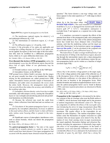
Figure P19 Three regions for propagation over the Earth. equation.
It is sometimes convenient to separate the effects of the
(1) The interference (optical) region, for which h ¢ > 0
t antenna from those of the propagation path, and a propagation
and pathlength difference d > l/8.
0 factor is then defined as the value of the pattern-propagation
(2) The intermediate (or transition) region, h ¢ > 0 and
t factor that would have been obtained with a broad-beam
d < l/8.
0 antenna, such that the underlying surface and the target are
(3) The diffraction region, h ¢ < 0 and d < l/8.
t 0 both fully illuminated. In the transition region (see propaga-
In region (1) the principles of ray optics are applicable and
tion over the earth), F can be calculated as the weighted sum
coverage has a lobing structure; in (2) and (3) ray optics can-
of a reflection factor F and a diffraction factor F .
not be applied. In region (2) the lower edge of the first reflec- R D
The main effects of radar coverage modification by F are
tion lobe must be modified by a diffraction propagation
the introduction of lobing in the interference region, descend-
factor, while in (3) a pure diffraction field exists. SAL
ing through the intermediate region into a deep propagation
Ref.: Skolnik (1980), p. 442; Barton (1988), pp. 288–302.
null in diffraction region. In the interference region the pat-
Over-[beyond-]the-horizon (OTH) propagation carries the tern-propagation factor can be written as a function of target
electromagnetic wave into the diffraction region (beyond the elevation angle F(q):
t
direct line of sight). Either of two phenomena may be
(
f q )
r
exploited: F q() f q() 1 += ------------Drexp – ( ja )
R t t f q
()
(1) Ground (surface) waves, typically in the VHF band. t
(2) Ionospheric bounce, in the HF band. where f (q) is the antenna voltage pattern at the target angle,
t
VHF ground waves follow Earth’s curvature, but the ranges f (q) is the voltage pattern at the angle of the reflected ray, D
r
are not great (usually less than a few hundred km). Radars is the divergence factor of the surface, r is the magnitude of
relying on this phenomenon are called ground-wave OTH the reflection coefficient, a is the phase of the reflected ray,
radars. Ionospheric bounce provides ranges of thousands of and the term in brackets is the propagation factor. More
kilometers, and under some circumstances the waves circle detailed formulas and analytical approximations used to com-
the entire Earth. However, this propagation mode suffers pute the pattern-propagation factor can be found in Barton
from several effects that reduce the accuracy and reliability of (1993), and more rigorous procedures are discussed in Meeks
the resulting radar data: (1982). SAL
(1) Ionospheric electron density varies from day to night, Ref.: IEEE (1993), p. 923; Blake (1980), p. 239; Meeks (1982); Barton
seasonally, and with sunspot activity, causing the ionospheric (1988), pp. 288–302, (1993), p. 145.
layers to vary in height and introducing physical and geomet- Propagation in the troposphere is determined by the dielec-
rical limitations on reflected paths. tric constant of the air (average value near the Earth surface e
(2) Because the reflected rays reach the earth from = 1.00075), which decreases with height and by the presence
above, clutter reflections from both land and sea surfaces are of random irregularities with different values of e The regu-
.
large. lar component of e efines the effects of the wave path varia-
d
(3) Calculation of the pattern-propagation factor is com- tion introducing the errors in range measurement about 90m
plicated by the ionospheric phenomena involved, in addition maximum, angle measurement due to refraction 30 arc-min
to the usual surface effects, and this factor is often well below maximum. The regular effects in the troposphere do not
unity (unless some focusing effect is present in the iono- depend on radar frequency. The random troposphere irregu-
sphere). larities cause the fluctuation of regular correction in a path
(4) Significant sources of atmospheric interference exist, variation with root-mean-square error about 0.15m, the fluc-
such as aurora borealis, which can distort the propagation tuation of wave front causing errors in angle measurement,
medium. SAL the signal amplitude fluctuation (fading) and refraction fluc-
Ref.: Blake (1980), p. 425; Kolosov (1987), Ch. 2. tuations including the appearance of abnormally large angles
The pattern-propagation factor is “the ratio of the signal (the effect of far troposphere propagation). In the bands of
strength that is actually present at a point in space to that centimeter waves and especially millimeter waves there are
which would have been present if free-space propagation had considerable effects of wave attenuation by hydrometeors and
occurred with the antenna beam directed toward the point in molecules of gases O and H O, which has a strong fre-
2
2