
Page 327 - Radar Technology Encyclopedia
P. 327
317 pulse compression, frequency-modulated [FM] pulse compression, phase-coded
in time on filter frequency is a linearly decreasing function of use a nonlinear FM waveform, in which the transmitted spec-
frequency (Fig. P27d). The linear characteristic of delay in trum is weighted, providing a low-sidelobe response with a
time provides large delay of low-frequency components at the matched filter. AIL
beginning of the pulse in comparison with high-frequency Ref.: Cook (1967), Chs. 6, 7; Rihaczek (1969), Ch. 7.
components at its end.
Phase-coded pulse compression uses phase-coded wave-
All spectral components are delayed in an optimum filter
forms. With pseudorandom phase-coding having n subpulses,
as well as during digital processing by the amount of time
the ratio of the mainlobe power over the average sidelobes is
necessary to arrive simultaneously at its output. Having the
approximately n. Therefore, for large n, on the order of a
same zero phase, they add to form a peak signal blip
thousand, sidelobes are small and measures to correct them
(Fig. P27e). This also explains the increase of signal ampli-
are not called for.
tude after passing through the filter and the compression in
Frequency signal compression is carried out in a correla-
width. The output pulse at a level -4 dB below the maximum
tor. To compress a complex signal in frequency it is necessary
has width t = 1/Df. The ratio of pulse width at the input t to to compensate for signal phase. To do this one must supply a
o
i
width at the output t for an optimum filter is called the pulse copy of the signal to the correlator synchronously and in
o
compression ratio, k = t/t = tD. phase. One thereby removes intrapulse modulation and the
i o
i
pc
spectral width of a signal with duration t will equal f = 1/t i
s
i
following compression. Thus, the correlator performs spec-
trum compression.
To the same degree that time compression improves
range resolution, frequency compression improves velocity
resolution. By using the combined correlation-filter method
of complex signal processing, one can accomplish compres-
sion in both time and frequency.
The compression ratio of a phase-keyed signal k pc = t /t
i o
is equal to the number of increments n (in the example of
Fig. P28, n = 7).
Thus, compression of phase-keyed signals in time sub-
stantially improves radar range resolution for a given average
transmitted power. Range resolution is determined by dura-
tion of the compressed pulse t and duration of the com-
o
pressed pulse will depend on spectral width of the complex
signal. For a phase-coded signal the spectral width is deter-
mined by the equation f = 1/t.
s
0
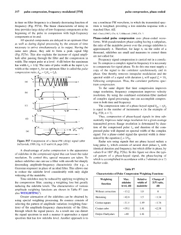
Figure P27 Compression of a linear-FM (chirp) signal (after Radar sets using signals that are phase keyed radiate a
Fal’kovich, 1989, Fig. 6.13 and 6.14, page 245). long pulse t, which consists of several short pulses t with
o
i
identical duration and frequency, but which differ in phase, by
A disadvantage of pulse compression is the appearance
values 0 or 180°(Fig. P28a). In this figure we show the typi-
of sidelobes in the compressed signal that can lower the radar
cal pattern of a phase-keyed signal, the phase-keying of
resolution. To control this, special measures are taken. To
which is accomplished in accordance with a 7-element (n = 7)
reduce sidelobes one can use a filter with smooth but sharply
Barker code.
descending amplitude-frequency characteristic (for e.g., a
Gaussian response) in place of an ideal filter. This allows one Table P7
to reduce the sidelobe level considerably with only slight
Characteristics of Pulse Compression Weighting Functions
widening of the mainlobe.
Time sidelobes may be reduced by applying weighting in Weighting Max. Relative Change of
the compression filter, causing a weighting loss but greatly sidelobe width of S/N ratio,
function
reducing the sidelobe levels. The characteristics of various level, dB mainlobe dB
amplitude weighting functions are shown in Table P7 (see
Without correction - 13.2 1.0 0
also WEIGHTING’).
Greater attenuation of the sidelobes can be obtained by Hamming - 42.8 1.5 - 1.34
using special weighting processing. Its essence consists of
selecting the pattern of amplitude variation (weighting func- Cosine-square - 31.4 1.59 - 1.76
tion) of the amplitude-frequency characteristic of the filter, Cosine-cube - 39.1 1.41 - 2.38
through which the signal passes. As a result one can distort
the signal spectrum in such a manner it approaches a signal Dolph-Chebyshev - 40 1.41 -
spectrum that has low sidelobe level. Another approach is to