
Page 326 - Radar Technology Encyclopedia
P. 326
pulse compression, analog pulse compression, frequency-modulated [FM] 316
Table P6
Characteristics of Passive Linear-FM Devices
(from Skolnik, 1990, Table 10.2, p. 10.13, reprinted by permission of McGraw-Hill)
The main disadvantages of analog pulse compression are
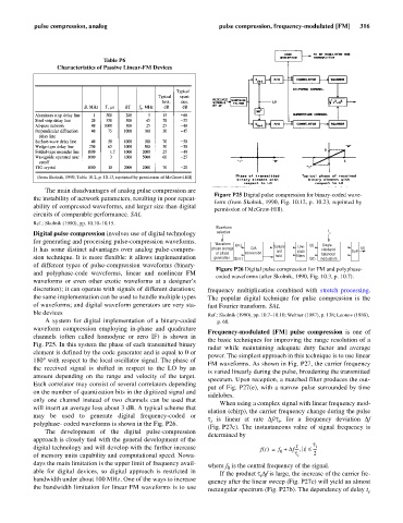
Figure P25 Digital pulse compression for binary-coded wave-
the instability of network parameters, resulting in poor repeat-
form (from Skolnik, 1990, Fig. 10.12, p. 10.23, reprinted by
ability of compressed waveforms, and larger size than digital
permission of McGraw-Hill).
circuits of comparable performance. SAL
Ref.: Skolnik (1990), pp. 10.10–10.15.
Waveform
Digital pulse compression involves use of digital technology selection f c
for generating and processing pulse-compression waveforms. Waveform I(n ) I(t) Single-
t
It has some distinct advantages over analog pulse-compres- phase storage D/A Sample Low- sideband Sum f(t)
and
pass
or phase conversion balanced
sion technique. It is more flexible: it allows implementation generation Q(n ) t hold filters Q(t) modulators
of different types of pulse-compression waveforms (binary-
Figure P26 Digital pulse compression for FM and polyphase-
and polyphase-code waveforms, linear and nonlinear FM
coded waveforms (after Skolnik, 1990, Fig. 10.3, p. 10.7).
waveforms or even other exotic waveforms at a designer’s
discretion); it can operate with signals of different durations; frequency multiplication combined with stretch processing.
the same implementation can be used to handle multiple types The popular digital technique for pulse compression is the
of waveforms; and digital waveform generators are very sta- fast Fourier transform. SAL
ble devices Ref.: Skolnik (1990), pp. 10.7–10.10; Wehner (1987), p. 138; Leonov (1988),
A system for digital implementation of a binary-coded p. 68.
waveform compression employing in-phase and quadrature
Frequency-modulated [FM] pulse compression is one of
channels (often called homodyne or zero IF) is shown in
the basic techniques for improving the range resolution of a
Fig. P25. In this system the phase of each transmitted binary
radar while maintaining adequate duty factor and average
element is defined by the code generator and is equal to 0 or
power. The simplest approach in this technique is to use linear
180° with respect to the local oscillator signal. The phase of
FM waveforms. As shown in Fig. P27, the carrier frequency
the received signal is shifted in respect to the LO by an
is varied linearly during the pulse, broadening the transmitted
amount depending on the range and velocity of the target.
spectrum. Upon reception, a matched filter produces the out-
Each correlator may consist of several correlators depending
put of Fig. P27(e), with a narrow pulse surrounded by time
on the number of quantization bits in the digitized signal and
sidelobes.
only one channel instead of two channels can be used that
When using a complex signal with linear frequency mod-
will insert an average loss about 3 dB. A typical scheme that
ulation (chirp), the carrier frequency change during the pulse
may be used to generate digital frequency-coded or
t is linear at rate Df/t, for a frequency deviation Df
i
i
polyphase- coded waveforms is shown in the Fig. P26.
(Fig. P27c). The instantaneous value of signal frequency is
The development of the digital pulse-compression
determined by
approach is closely tied with the general development of the t
t
digital technology and will develop with the further increase ft () f += 0 Df ---- t £ ---- i
,
of memory units capability and computational speed. Nowa- t i 2
days the main limitation is the upper limit of frequency avail- where f is the central frequency of the signal.
0
able for digital devices, so digital approach is restricted in If the product tDf is large, the increase of the carrier fre-
i
bandwidth under about 100 MHz. One of the ways to increase quency after the linear sweep (Fig. P27c) will yield an almost
the bandwidth limitation for linear FM waveforms is to use rectangular spectrum (Fig. P27b). The dependency of delay t e