
Page 328 - Radar Technology Encyclopedia
P. 328
pulse compression, phase-coded pulse repetition frequency, high (HPRF) 318
ent PRFs are required to eliminate range ambiguity. Eclipsing
losses are appreciable, and sensitivity time control cannot be
used, resulting in requirements for the receiver to handle a
wide range of amplitudes. The advantages are that doppler
measurement is unambiguous (so blind speeds do not occur
from ambiguous target doppler within the main-beam clutter
notch), and long transmitter pulses are not required to obtain
high average power. The MPRF to large extent is a compro-
mise mode between LPRF and HPRF, so it tends to share both
advantages and disadvantages of these modes.
Since the requirements to the proper choice of optimal
PRF are contradictory, a useful mode of radar operation is
staggered PRF (i.e., the mode when several different PRFs
are used in a definite sequence). Sometimes this mode is
called multiple PRFs and when the interpulse interval varies
in a random manner it is termed PRF jitter. Pulse trains
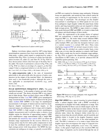
Figure P28 Compression of a phase-coded signal. employing staggered PRF are termed staggered pulse trains.
The PRF may be switched on a pulse-to-pulse basis, every
Biphase waveforms (phase-coded by 180°) using binary other scan, or every time the antenna is scanned a half beam-
pseudorandom sequences have been most popular. As with a width. Such a mode may be used to eliminate range ambigu-
chirp pulse, a phase-coded signal is compressed by using a ity (Fig. P29), to improve the characteristics of blind speed
matched filter (Fig. P28c). It consists of a delay line with taps, cancellation in MTI radars, or to provide enhanced ECCM
phase inverters (p), adder (S), and filter (F). In Fig. P28d we capability against jamming. SAL
have shown pulses which come from taps of the delay line to Ref.: IEEE (1990), pp. 23, 20, 21,18; Johnston (1979), pp. 64, 67; Barton
the adder. The result of summation is shown in Fig. P28e, and (1991), p. 7.44; Skolnik (1980), p. 114; Long (1992), p. 259; Chrza-
in Fig. P28f we obtain an envelope of a signal t at the filter nowski (1990), p. 60; Neri (1991), p. 421; Nathanson (1990), p. 330.
o
output F, that is compressed relative to t by the factor n. AIL
i
Ref.: Cook (1967), Ch. 8; Popov (1980), p. 105; Sosulin (1992), p. 40.
The pulse-compression ratio is the ratio of transmitted
pulsewidth to the pulsewidth after the process of pulse com-
pression (at the output of the matched filter). An alternative
term used is time-bandwidth product, although this term is
also applicable to uncompressed waveforms (e.g., pulse
trains). SAL
Ref.: Barton (1988), p. 221.
PULSE REPETITION FREQUENCY (PRF). The pulse
repetition frequency “is the number of pulses per unit of time,
usually per second.” The choice of proper PRF is very impor-
Figure P29 Removal of range ambiguity with staggered PRF
tant in radar design. There are three classic cases of PRFs are
(from Long, 1992, Fig. 6.15, p. 254).
distinguished in radar: Low PRF (LPRF) gives unambiguous
range measurements for all the targets of interest for the given
High PRF (HPRF) has a special meaning for pulsed doppler
radar; medium PRF (MPRF) is too large for unambiguous
radar: a pulsed doppler radar with a HPRF waveform is
measurement of all targets of interest and too small for unam-
unambiguous in doppler but totally ambiguous in range. This
biguous doppler measurement of these targets, so the
is highly desirable for those cases in which targets can be dis-
expected targets are ambiguous both in range and in doppler.
tinguished from clutter on the basis of radial velocity. For this
High PRF (HPRF) is high enough to obtain unambiguous
reason HPRF waveforms have found extensive application in
doppler measurement (and, in airborne radar, to obtain a clear
airborne radar, where the strongest clutter return lies at a
doppler region for detection of approaching targets). LPRF
range no closer than the aircraft altitude, and all mainlobe and
gives unambiguous range measurement with a single PRF
sidelobe clutter is located in the doppler frequency region
and permits use sensitivity time control (STC) to reduce the
± 2v /l, where v is the velocity of the radar-equipped air-
r
r
dynamic range requirements for the receiver. However, the
craft. The PRF is selected so as to create a large clutter-free
average power may be low unless pulse compression is used
doppler region that encompasses the range of expected clos-
to meet the combined needs of good range resolution and
ing velocities. Range ambiguities occur every c/2f meters,
r
high average power (with long pulses). For HPRF the mea-
where c is the speed of light and f is the waveform PRF, but
r
surements are ambiguous in range, so typically several differ-
target range, if required, can be resolved through the use of