
Page 317 - Radar Technology Encyclopedia
P. 317
307 polarization parameter measurement POWER
argument of the phasor, Stoke’s parameters). The main meth- such that the polarization ratio is larger for the echo from a
ods of measurement are shown in Table P3. The first two are cell containing a desired target, and smaller when the return
used to measure the parameters of full-polarized waves, while arrives from cells containing undesired targets or clutter only.
the last three can be also applied also to partially-polarized The polarization ratio discriminant is a vector discrimination
waves (having a polarization component of random ori- technique. SAL
gin).IAM Ref.: Currie (1987), p. 285.
Ref.: Kanareikin (1966), p. 107.
The polarization response is the polarization received by
antenna in response to a signal transmitted with preset polar-
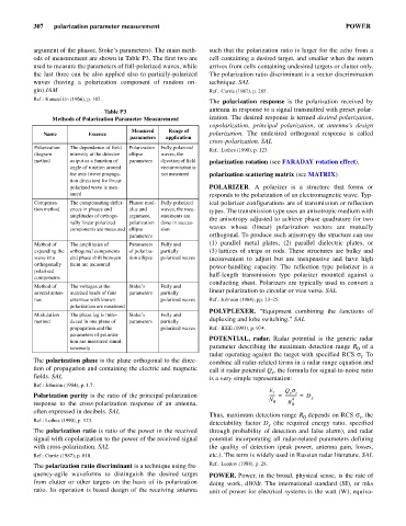
Table P3
Methods of Polarization Parameter Measurement ization. The desired response is termed desired polarization,
copolarization, principal polarization, or antenna’s design
Measured Range of
Name Essence polarization. The undesired orthogonal response is called
parameters application
cross-polarization. SAL
Polarization The dependence of field Polarization Fully polarized
Ref.: Lothes (1990), p. 123.
diagram intensity at the detector ellipse waves, the
method output as a function of parameters direction of field polarization rotation (see FARADAY rotation effect).
angle of rotation around vector rotation is
the axis (wave propaga- not measured polarization scattering matrix (see MATRIX).
tion direction) for linear
polarized wave is mea- POLARIZER. A polarizer is a structure that forms or
sured responds to the polarization of an electromagnetic wave. Typ-
Compensa- The compensating differ- Phasor mod- Fully polarized ical polarizer configurations are of transmission or reflection
tion method ences in phases and ulus and waves, the mea-
types. The transmission type uses an anisotropic medium with
amplitudes of orthogo- argument, surements are the anisotropy adjusted to achieve phase quadrature for two
nally linear polarized polarization done in succes-
components are measured ellipse sion waves whose (linear) polarization vectors are mutually
parameters orthogonal. To produce such anisotropy the structure can use
Method of The amplitudes of Parameters Fully and (1) parallel metal plates, (2) parallel dielectric plates, or
expanding the orthogonal components of polariza- partially (3) lattices of strips or rods. These structures are bulky and
wave into and phase shift between tion ellipse polarized waves inconvenient to adjust but are inexpensive and have high
orthogonally them are measured
power-handling capacity. The reflection type polarizer is a
polarized
components half-length transmission type polarizer mounted against a
conducting sheet. Polarizers are typically used to convert a
Method of The voltages at the Stoke’s Fully and
several anten- matched loads of four parameters partially linear polarization to circular or vice versa. SAL
nas antennae with known polarized waves Ref.: Johnson (1984), pp. 23–25.
polarization are measured
POLYPLEXER. “Equipment combining the functions of
Modulation The phase lag is intro- Stoke’s Fully and
method duced in one plane of parameters partially duplexing and lobe switching.” SAL
propagation and the polarized waves Ref.: IEEE (1993), p. 974.
parameters of polariza-
tion are measured simul- POTENTIAL, radar. Radar potential is the generic radar
taneously parameter describing the maximum detection range R of a
0
radar operating against the target with specified RCS s. To
t
The polarization plane is the plane orthogonal to the direc- combine all radar-related terms in a radar range equation and
tion of propagation and containing the electric and magnetic call it radar potential Q , the formula for signal-to-noise ratio
r
fields. SAL is a very simple representation:
Ref.: Johnson (1984), p. 1.7.
E 1 Q s
r t
Polarization purity is the ratio of the principal polarization ------ = ----------- = D
N 0 4 x
response to the cross-polarization response of an antenna, R 0
often expressed in decibels. SAL
Thus, maximum detection range R depends on RCS s, the
0
t
Ref.: Lothes (1990), p. 123.
detectability factor D (the required energy ratio, specified
x
The polarization ratio is ratio of the power in the received through probability of detection and false alarm), and radar
signal with copolarization to the power of the received signal potential incorporating all radar-related parameters defining
with cross-polarization. SAL the quality of detection (peak power, antenna gain, losses,
Ref.: Currie (1987), p. 810. etc.). The term is widely used in Russian radar literature. SAL
The polarization ratio discriminant is a technique using fre- Ref.: Leonov (1988), p. 28.
quency-agile waveforms to distinguish the desired target POWER. Power, in the broad, physical sense, is the rate of
from clutter or other targets on the basis of its polarization doing work, dW/dt. The international standard (SI), or mks
ratio. Its operation is based design of the receiving antenna unit of power for electrical systems is the watt (W), equiva-