
Page 312 - Radar Technology Encyclopedia
P. 312
phase shifter, field-effect tetrode phase shifter, mechanical 302
beneficial for the formation of microwave phase-coded wave-
forms and using in broadband phased arrays. IAM
f 0 f + f c f 0 f
0
Ref.: Gassanov (1988), p. 151. 1st 2nd
mixer mixer
A field-effect transistor (FET) phase shifter is a semicon-
ductor phase shifter based on a field-effect transistor as the
main active component. Typically, it is used as a discrete
phase shifter, having a configuration analogous to the diode f c Delay
phase shifter, and incorporates additional matching circuits t f c f
because of the large shunting reactive resistance of the inter-
electrode area. The loss at X-band is about 5 to 11 dB. To Figure P10 Schematic diagram of the Huggins phase shifter
compensate for manufacturing differences, frequency and (after Skolnik, 1980, Fig. 8.19, p. 304).
temperature dependence of phase shifter performance, com-
bined discrete-analog phase shifters with programmable con- integrated phase shifters are made with one type of microstrip
trol are used. The control is implemented by the gradual line, most often asymmetrical strip, but in modern devices
variation of the transistor bias voltage (0 to 3V). Field-effect with different types of lines, slotted, coplanar, and so forth,
transistor phase shifters are characterized by a low switch that form a phase shifter in the form of a three-dimensional
time and a wide bandwidth and are good for use in broadband integrated circuit.
phased arrays. IAM Most common are circuits of reflex phase shifters with
Ref.: Ayasli, Y., et al., IEEE Trans MTT-32, No. 12, 1984. parallel connection to an asymmetrical stripline of serial
diode circuits: varactor diode and correcting inductance coil
A fixed phase shifter provides a constant phase shift. Typi-
in the form of a loop. A 360° phase shifter contains two iden-
cally, this type of phase shifter is based on a delay line. It is
tical serial diode circuits connected to a line at a distance of a
possible to realize any desired phase shift and there are practi-
quarter-wavelength from one another.
cally no limitations for input signal dynamic range (more than
A phase shifter based on a combination of different lines,
100 dB). For frequencies of 0.3 to 40 GHz, striplines, micros-
for example an asymmetrical strip and symmetrical slot, has
trip lines, and coaxial lines are used, while for frequencies
diodes connected, respectively, to an aperture of the strip con-
more than 40 GHz, waveguides are used. The accuracy of
nector and a short-circuited slot line located orthogonally to it
phase shifting in the range of 0 to 360° is several percent and
on the opposite side of the substrate.
less. IAM
These reflex phase shifters in combination with quadra-
Ref.: Sokolov (1984), p. 122.
ture directional couplers create the component base of inte-
A Fox phase shifter is a mechanical waveguide phase shifter grated transfer phase shifters.
with mechanical phase shift control by rotation of one section Integrated phase shifters are marked by their small
of transmission line relative to another one. It is used prima- dimensions, and are used in radar control devices, and in sig-
rily in measurement equipment. IAM nal processing devices where high power-handling capacity is
Ref.: Lavrov (1974), p. 344; Gardiol (1984), p. 253. not required. IAM
A helical phase shifter is a nonreciprocal ferrite phase shifter Ref.: Gvozdev, V. I., Radiotekhnika, no. 4, 1991, p. 33, in Russian.
consisting of shielded helix wound on a ferrite toroid for A latching phase shifter is a reciprocal ferrite phase shifter
compactness at frequencies below the S-band. The unit can be in which the magnetic state of the ferrite is set with a current
either analog or digital. A typical 4-bit digital latching phase pulse, leaving the remanent magnetization constant until reset
shifter at S-band has an insertion loss of 1.2 dB, peak-power by another current pulse. This mode of operation eliminates
handling capability about 10 kW and provides 360° of phase the constant drive dissipation between phase settings, and the
shift. IAM possibility of undesired phase modulation resulting from cur-
Ref.: Skolnik (1970), p. 12.21. rent fluctuation during transmission and signal reception.
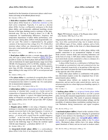
A Huggins phase shifter is one using a frequency change DKB
technique to introduce the required phase shift, with the sub- Ref.: Skolnik (1970), p. 12.11.
sequent conversion back to the input frequency. It consists of A mechanical phase shifter is based on the variation of elec-
two mixers and a delay line (Fig. P10). The signal at fre- trical length of transmission line by changing its geometrical
quency f is mixed with a signal from the variable frequency length or cross section or by inserting in a waveguide dielec-
0
oscillator f in the first mixer. The phase-shifted signal from tric or ferromagnetic plates (see waveguide phase shifter).
c
the output of delay line and the signal from the first mixer are An example of a mechanical phase shifter is the Fox phase
mixed in the following stage to obtain the resultant signal shifter. Mechanical phase shifters have low phase shifting
with the same frequency f and phase shift f = 2pf t. SAL speed (hundreds of hertz) and are not used in modern radars.
c
0
Ref.: Skolnik (1980), p. 303. IAM
An integrated(-circuit) phase shifter is a semiconductor Ref.: Skolnik (1962), p. 308; Sazonov (1988), p. 152.
phase shifter in the form of an integrated circuit. Structurally,