
Page 310 - Radar Technology Encyclopedia
P. 310
PERMITTIVITY phase shifter, [combined] coaxial-line-waveguide 300
PERMITTIVITY. Permittivity is “the incremental change in shifters provide higher power handling capacity and have
electric displacement per unit electric field when the magni- lower loss at frequencies above about 2 GHz. Integrated cir-
tude of the measuring filed is very small compared to the cuit phase shifters and those based on new physical principles
coercive electric field. The small signal relative permittivity, (e.g., plasma phase shifters) are promising in certain applica-
k is equal to the ratio of the absolute permittivity e to the per- tions.
/
mittivity of free space, that is k = ee.” The relative permit- Phase shifters are widely used in phased-array radar, and
0
tivity is also called the relative dielectric constant, denoted by other applications include generation of phase-coded wave-
- 9
e. The permittivity of fee space is e = 10 /36p = 8.854 ´ forms, monopulse tracking circuits, and others. SAL
0
r
-12
10 F/m. DKB Ref.: IEEE (1993), p. 944; Skolnik (1970), Ch. 12; Gassanov (1988), p. 146;
Ref.: IEEE (1993), p. 936. Lavrov (1974), p. 340; Koul (1991, 1992).
PHASED ARRAY (see ARRAY ANTENNA). Table P1
Classification of Phase Shifters
PHASE. Phase is a property of a periodic phenomenon f(t)
with a period T, defined at time t as “the fractional part t/T of Electrical phase shifters
the period T through which t has advanced relative to an arbi- Ferrite phase shifters:
trary origin.” In radar applications, the concept of phase is
(a) Nonreciprocal Toroidal [twin-slab], strip-
usually applied to oscillation of electromagnetic waves. (See
line, coaxial- waveguide,
OSCILLATION, sinusoidal.) SAL
helical
Ref.: IEEE (1993), p. 939.
(b) Reciprocal Reggia-Spencer, Faraday
The blind phase is a phenomenon observed in MTI systems
rotator
when “the echo of interest is in quadrature to the reference
Semiconductor phase PN diode, PIN diode, inte-
signal.” It occurs in systems that have only the in-phase chan-
shifters grated circuit
nel, and can be eliminated by using in-phase/quadrature (I/Q)
channels in the signal processor. SAL Huggins phase shifter
Ref.: Schleher (1978), p. 8.
Mechanical phase shifters Fox phase shifter, helical
phase front (see WAVE front). line, waveguide trombone
PHASE SHIFTER. A phase shifter is “a device in which An active phase shifter is one that includes amplification
output voltage (or current) may be adjusted, in use or in its along with phase shifting. Examples are field-effect tetrode
design, to have some desired phase relation with the input and field-effect transistor phase shifters. If the phase shift is
voltage (or current).” The operation of phase shifters is usu- provided without amplification, the phase shifter is termed
ally based on the variation of the electrical length of a trans- passive. SAL
mission line, connection of a reactive element to a Ref.: Gassanov (1988), p. 146.
transmission line, or vector addition of several signals. Phase
A capacitance phase shifter is the phase shifter inverting the
shifters can be classified as
phase because of variation in capacitance. The most widely
(1) Electrical or mechanical, depending on the physical
used are the semiconductor phase shifters employing the vari-
principle of phase control;
ation of the PN junction capacitance. IAM
(2) Analog (continuous) or digital (discrete), depending
Ref.: Popov (1980), p. 125; Skolnik (1970), p. 12.55; Sazonov (1988), p. 178.
on the granularity of control;
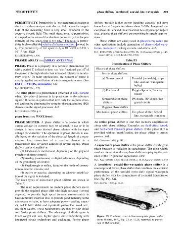
(3) Feedthrough or reflex, based on the mode of connec- A [combined] coaxial-line-waveguide phase shifter is a
tion to external circuits; and nonreciprocal ferrite phase shifter that combines the electrical
(4) Active or passive, depending on whether amplifica- performance of the toroidal (twin-slab) digital waveguide
tion of the signal is included. phase shifter with the compactness of a coaxial transmission
The main types of microwave phase shifters are shown in line (Fig. P9). SAL
Table P1 Ref.: Skolnik (1970), p. 12-21.
The main requirements on modern phase shifters are to
provide the required phase shift with high accuracy (several
degrees), to provide high speed (several nanoseconds), to
have minimum insertion loss, to provide good matching to the
microwave circuits, to have adequate power-handling capac-
ity, and to have stable and repeatable parameters, small size,
and light weight. These requirements are met by both diode
and ferrite phase shifters. The advantage of diode types is
lower weight and size, higher speed, and compatibility with Figure P9 Combined coaxial-line-waveguide phase shifter
integrated circuit technology and packaging. Ferrite phase (from Skolnik, 1970, Fig. 23, p. 12.25, reprinted by permis-
sion of McGraw-Hill).