
Page 308 - Radar Technology Encyclopedia
P. 308
pattern, array (antenna) pattern, multibeam 298
N 1–
h q
exp
f q() = å Ax ( ) [ jny q()] 2 q
a n 0 2 1
csc beam
n = 0
h m
giving maximum directivity for exp(jy (q)] = 1 at an angle:
0
l x ö
æ
,, ,
q = asin --- ------ + m , m = 0 1 2 ¼ (2) q
è
m d 2p ø Fan beam
Equation (2) is the basic formula showing the properties
R
of the array pattern:
(1) The pattern does not have a single maximum, but R m
rather a set of peaks corresponding to m = 1, 2, ... (called grat- 2
ing lobes), which must be suppressed by proper design Figure P5 Example of radar coverage using csc antenna (after
(choice of the element pattern and the ratio d/l). Barton, 1988, Fig. 4.2.9, p. 163).
(2) There are two means of scanning the array pattern
electronically: to change l (frequency scanning), or the ele- The same pattern, inverted, is used in airborne surface-
ment-to-element phase shift x (phase scanning). search radar (see COVERAGE, radar). DKB
For a two-dimensional planar array of n ´ m elements Ref.: Skolnik (1980), p. 258; Barton (1988), pp. 26–27.
having aperture illumination A exp(jf ), the array factor is The difference pattern of a monopulse antenna is the error-
nm
nm
sensing pattern formed, in a simple feed, by subtracting the
N 1– M – 1
signal voltage of the lower horns from that of the upper. In
f uv ,( ) = å å A nm × exp [ j f( nm + kx u + ky v )]
a
n
m
more complex feed systems, the difference pattern is formed
n = 0 m = 0 by coupling of horns or array elements to produce an illumi-
where u, v are sine-space coordinates and x , y are linear nation function with odd symmetry and with a shape designed
n
m
coordinates of the nmth element in the array plane. SAL to create the steepest possible slope about the center null, for
Ref.: Johnson (1984), pp. 20.3–20.17. given sidelobe levels.
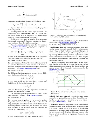
Figure P6 shows the antenna sum pattern formed using a
The array element pattern is “the actual radiation pattern of
cosx illumination function on a rectangular aperture, and the
an element in the array taken in the presence of all other ele-
difference pattern representing the first derivative of the sum
ments and taking into account all mutual coupling effects and
pattern, formed with an illumination function xcosx. (See also
mismatches.” (See array (antenna) pattern.) SAL
MONOPULSE.) DKB
Ref.: Johnson (1984), p. 20.27.
Ref.: Barton (1988), pp. 198–205.
The Bickmore-Spellmire pattern, produced by the Bick-
more-Spellmire distribution, is given by 1
2 2
Eu () = L p( u – A ) 0.5
Voltage 0
where L is the lambda function, p and A are the constants of
the Bickmore-Spellmire distribution, and
0.5
pDsin q
u = ------------------- 1
l 2 1 0 1 2
Angle in beamwidths
Here, l is the wavelength, q s the angle from the normal to
i
aperture, and D is antenna diameter. Figure P6 Sum and difference patterns for cosine illumina-
The Bickmore-Spellmire pattern reduces to the Cheby- tion function.
shev pattern when p = -1/2. (See WEIGHTING.) SAL
A Dolph-Chebyshev pattern is the optimal antenna pattern
Ref.: Currie (1987), p. 533.
created by an aperture illumination of the Dolph-Chebyshev
The cosecant-squared pattern is an elevation pattern family, having minimum beamwidth for a given sidelobe
designed to obtain constant signal level, as a function of level. (See WEIGHTING.) DKB
range, on target at constant elevation relative to the radar. The
A multibeam pattern is the pattern of an antenna that radi-
mainlobe pattern is conventional, but above the half-power
ates more than one beam. In stacked-beam, three-dimensional
point, at angle q , the mainlobe skirt and sidelobes are
1 search radar multiple beams are generated in the elevation
replaced by a function (Fig. P5).
coordinate. In monopulse radar, multiple beams are generated
2
csc
q
æ
G q() G q ) -------------- ö in both azimuth and elevation, difference patterns being
=
(
1 è csc q ø
1 formed in both coordinates to supplement the on-axis sum
where G is antenna power gain and q is elevation angle. pattern. DKB