
Page 217 - Radiochemistry and nuclear chemistry
P. 217
Detection and Measurement Techniques 201
If 105 charge carrier pairs have formed in the detector and C = 100 pF, then AV = 0.16
mV. In practice the effective voltage drop A Vef f is somewhat less than the calculated AV.
8.2.2. Basic counting systems
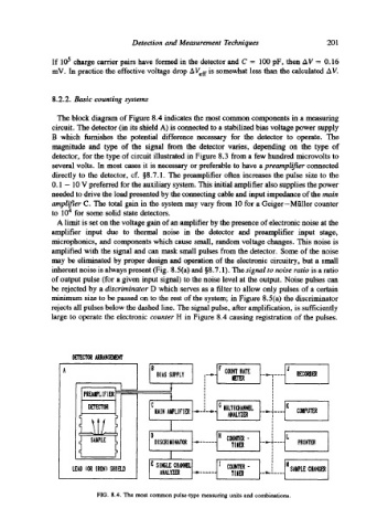
The block diagram of Figure 8.4 indicates the most common components in a measuring
circuit. The detector (in its shield A) is connected to a stabilized bias voltage power supply
B which furnishes the potential difference necessary for the detector to operate. The
magnitude and type of the signal from the detector varies, depending on the type of
detector, for the type of circuit illustrated in Figure 8.3 from a few hundred microvolts to
several volts. In most cases it is necessary or preferable to have a preamplifier connected
directly to the detector, cf. w The preamplifier often increases the pulse size to the
0.1 - 10 V preferred for the auxiliary system. This initial amplifier also supplies the power
neeMed to drive the load presented by the connecting cable and input impedance of the main
amplifier C. The total gain in the system may vary from 10 for a Geiger-Miiller counter
to 10 4 for some solid state detectors.
A limit is set on the voltage gain of an amplifier by the presence of electronic noise at the
amplifier input due to thermal noise in the detector and preamplifier input stage,
microphonics, and components which cause small, random voltage changes. This noise is
amplified with the signal and can mask small pulses from the detector. Some of the noise
may be eliminated by proper design and operation of the electronic circuitry, but a small
inherent noise is always present (Fig. 8.5(a) and w The signal to noise ratio is a ratio
of output pulse (for a given input signal) to the noise level at the output. Noise pulses can
be rejected by a discriminator D which serves as a filter to allow only pulses of a certain
minimum size to be passed on to the rest of the system; in Figure 8.5(a) the discriminator
rejects all pulses below the dashed line. The signal pulse, after amplification, is sufficiently
large to operate the electronic counter H in Figure 8.4 causing registration of the pulses.
DETECTOR ARR,~IGDIENT
B lr r RATE: J
B! AS SUPPLY llE"I'ER ,,-- Din,- ...... RECORDER
l I
t PREAIIPL F [ ER 1 t I ,
[
L lCaAIN ^~PLlrI~ I G MULTICHANNEL ._~,. ..... t K COMPUTER
~t~YZD
! I
I
D H C~NTB-
DISCRIMINATOR TIIIB -,-qt,-- f .... PRINTER
1 / : I
LEAD (OR IRON) SHIELD E SINGLE CHANNEL [ COUNTER- H SAIIPLg CHANGD
T[IID
ANALYZER
FIG. 8.4. The most common pulse-type measuring units and combinations.