
Page 221 - Radiochemistry and nuclear chemistry
P. 221
Detection and Measurement Techniques 205
is a function of the decrease in electric field near the anode due to the build-up of a layer
of slow-moving positive ions, and of the time constant circuitry (curve II in Fig. 8.3(b)).
The electric field strength at a distance x from the anode is proportional to 1/x. If the
applied voltage of a cylindrical chamber of 1 cm radius is 1000 V, the potential in the
immediate vicinity of a center wire of 0.0025 cm diameter is approximately 7 • 104 V
cm-1. As the primary electrons reach the vicinity of this high field and increase their
kinetic energy, they cause secondary ionization which increases the pulse detected at the
wire anode. The collected charge is given by (8.2), where a, the gas multiplication factor,
is~. 1.
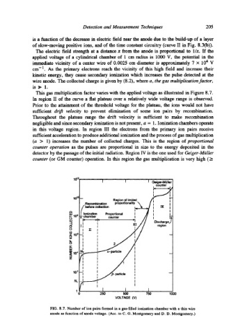
This gas multiplication factor varies with the applied voltage as illustrated in Figure 8.7.
In region II of the curve a flat plateau over a mlativdy wide voltage range is observed.
Prior to the attainment of the threshold voltage for the plateau, the ions would not have
sufficient drift velocity to prevent dimination of some ion pairs by recombination.
Throughout the plateau range the drift velocity is sufficient to make recombination
negligible and since secondary ionization is not present, a = 1. Ionization chambers operate
in this voltage region. In region III the electrons from the primary ion pairs receive
sufficient acceleration to produce additional ionization and the process of gas multiplication
(a > 1) increases the number of collected charges. This is the region of proportional
counter operation as the pulses am proportional in size to the energy deposited in the
detector by the passage of the initial radiation. Region IV is the one used for Geiger-Mgiller
counter (or GM counter) operation. In this region the gas multiplication is very high (_>
1012
GeigerAMLiller
counter
I I ,
lot0
Region of limited I I
Recombination proportionality
before collection
I I
o
u.I Ionization Proporlional I i !_
P.- 10 e c chamber counter I
0 L.
ILl r- IDischarge,~
::1 i llI
0 II ! region
0 I
z lOe~ I
o =
I
Iz I t I
uJ I
= N= ~~- padicle I I
z I I
I I
I I I I
102 --i I em~ particle I
I I I
N, I I
I I
I
0 250 500 750 1000
VOLTAGE (V)
FIG. 8.7. Number of ion pairs formed in a gas-filled ionization chamber with a thin wire
anode as function of anode voltage. (Acc. to C. G. Montgomery and D. D. Montgomery.)