Page 218 - Radiochemistry and nuclear chemistry
P. 218

202                 Radiochemistry and Nuclear Chemistry


                                                                   WINDOW
                                                                   WIDTH
                1


               I-- /   DISCRIMINATOR LEVEL
               "1-  /                                            a:i   i.,.   I   l
               m
                                                                 6i    ta.   #  t
               RI                                                JI    ,=   [   I
               ffl
               ..1
                                          NOISE
                                                                   I   I   -"
                                                                   I   i
                             ,,          ~
                                  TIME                              ENERGY (PULSE HEIGHT)
                             &                                     b
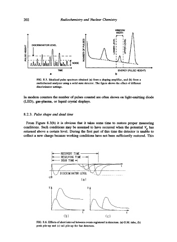
                      FIG.  8.5.  Idealized pulse  spectrum  obtained  (a) from a  shaping amplifier,  and  Co) from a
                      multichannel  analyzer using  a  solid state detector.  The  figure  shows the effect of different
                      discriminator  settings.

               In modern  counters  the number of pulses  counted are often  shown on light-emitting  diode
               (LED),  gas-plasma,  or  liquid  crystal displays.


               8.2.3.  Pulse shape and dead time

                From  Figure  8.3(b)  it  is  obvious  that  it  takes  some  time  to  restore  proper  measuring
               conditions.  Such  conditions  may  be  assumed  to  have  occurred  when  the  potential  Vp has
               returned  above  a  certain  level.  During  the  first  part  of this  time the  detector  is unable  to
               collect a new  charge because working  conditions  have not been  sufficiently  restored.  This


                                    RECOVERY  TIME      --~
                                                         ]
                               ~    RESOLVING  TIME----~,   i  1
                                    DEAD TIME~     I     ',
                                                   t


                                                          ...................................
                            -Vt                (a)

                                                   V


                                                t                        t
                                     (b)                     (c)
                      FIG. 8.6. Effects of short interval between events registered in detectors.  (a) G.M. tube,  (b)
                      peak  pile-up  and  (c) tail pile-up  for fast detectors.
   213   214   215   216   217   218   219   220   221   222   223