Page 22 - Rashid, Power Electronics Handbook
P. 22

1 Introduction                                                                                        5


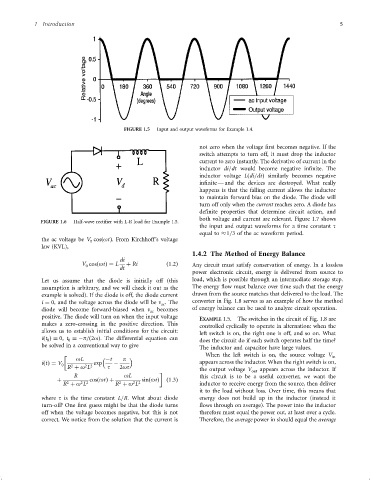
                                               FIGURE 1.5  Input and output waveforms for Example 1.4.


                                                                        not zero when the voltage ®rst becomes negative. If the
                                                                        switch attempts to turn off, it must drop the inductor
                                                                        current to zero instantly. The derivative of current in the
                                                                        inductor di=dt would become negative in®nite. The
                                                                        inductor voltage Lðdi=dtÞ similarly becomes negative
                                                                        in®nite Ð and the devices are destroyed. What really
                                                                        happens is that the falling current allows the inductor
                                                                        to maintain forward bias on the diode. The diode will
                                                                        turn off only when the current reaches zero. A diode has
                                                                        de®nite properties that determine circuit action, and
                                                                        both voltage and current are relevant. Figure 1.7 shows
                    FIGURE 1.6  Half-wave recti®er with L-R load for Example 1.5.
                                                                        the input and output waveforms for a time constant t
                                                                        equal to  1=3 of the ac waveform period.
                    the ac voltage be V cosðotÞ. From Kirchhoff's voltage
                                    0
                    law (KVL),
                                                                      1.4.2 The Method of Energy Balance
                                              di
                                 V cosðotÞ¼ L   þ Ri         ð1:2Þ    Any circuit must satisfy conservation of energy. In a lossless
                                   0
                                              dt
                                                                      power electronic circuit, energy is delivered from source to
                    Let us assume that the diode is initially off (this  load, which is possible through an intermediate storage step.
                    assumption is arbitrary, and we will check it out as the  The energy ¯ow must balance over time such that the energy
                    example is solved). If the diode is off, the diode current  drawn from the source matches that delivered to the load. The
                    i ¼ 0, and the voltage across the diode will be v . The  converter in Fig. 1.8 serves as an example of how the method
                                                            ac
                    diode will become forward-biased when v  becomes  of energy balance can be used to analyze circuit operation.
                                                        ac
                    positive. The diode will turn on when the input voltage
                                                                        EXAMPLE 1.5.  The switches in the circuit of Fig. 1.8 are
                    makes a zero-crossing in the positive direction. This
                                                                        controlled cyclically to operate in alternation: when the
                    allows us to establish initial conditions for the circuit:
                                                                        left switch is on, the right one is off, and so on. What
                    iðt Þ¼ 0, t ¼ÿp=ð2oÞ. The differential equation can
                      0      0                                          does the circuit do if each switch operates half the time?
                    be solved in a conventional way to give
                                                                        The inductor and capacitor have large values.
                                                                          When the left switch is on, the source voltage V
                                                                                                                     in
                               oL         ÿt   p
                    iðtÞ¼ V 0        exp    ÿ                           appears across the inductor. When the right switch is on,
                            R þ o L       t   2ot
                              2
                                  2 2
                                                                        the output voltage V out  appears across the inductor. If

                               R               oL                       this circuit is to be a useful converter, we want the
                         þ          cosðotÞþ         sinðotÞ  ð1:3Þ
                                                  2 2
                                              2
                                 2 2
                            2
                           R þ o L          R þ o L                     inductor to receive energy from the source, then deliver
                                                                        it to the load without loss. Over time, this means that
                    where t is the time constant L=R. What about diode  energy does not build up in the inductor (instead it
                    turn-off? One ®rst guess might be that the diode turns  ¯ows through on average). The power into the inductor
                    off when the voltage becomes negative, but this is not  therefore must equal the power out, at least over a cycle.
                    correct. We notice from the solution that the current is  Therefore, the average power in should equal the average
   17   18   19   20   21   22   23   24   25   26   27