
Page 24 - Rashid, Power Electronics Handbook
P. 24
1 Introduction 7
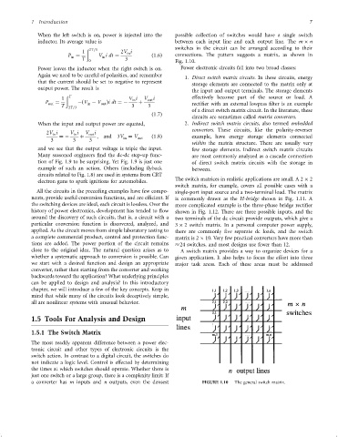
When the left switch is on, power is injected into the possible collection of switches would have a single switch
inductor. Its average value is between each input line and each output line. The m n
switches in the circuit can be arranged according to their
ð 2T=3
1 2V i
in
P ¼ V idt ¼ ð1:6Þ connections. The pattern suggests a matrix, as shown in
in
in
T 0 3 Fig. 1.10.
Power leaves the inductor when the right switch is on. Power electronic circuits fall into two broad classes:
Again we need to be careful of polarities, and remember
1. Direct switch matrix circuits. In these circuits, energy
that the current should be set to negative to represent storage elements are connected to the matrix only at
output power. The result is
the input and output terminals. The storage elements
1 ð T V i V out i effectively become part of the source or load. A
in
P ¼ ÿðV ÿ V Þidt ¼ÿ þ
out in out recti®er with an external lowpass ®lter is an example
T 2T=3 3 3
of a direct switch matrix circuit. In the literature, these
ð1:7Þ
circuits are sometimes called matrix converters.
When the input and output power are equated, 2. Indirect switch matrix circuits, also termed embedded
converters. These circuits, like the polarity-reverser
2V i V i V out i
in
in
¼ÿ þ ; and 3V ¼ V out ð1:8Þ example, have energy storage elements connected
in
3 3 3
within the matrix structure. There are usually very
and we see that the output voltage is triple the input. few storage elements. Indirect switch matrix circuits
Many seasoned engineers ®nd the dc-dc step-up func- are most commonly analyzed as a cascade connection
tion of Fig. 1.9 to be surprising. Yet Fig. 1.9 is just one of direct switch matrix circuits with the storage in
example of such an action. Others (including ¯yback between.
circuits related to Fig. 1.8) are used in systems from CRT
The switch matrices in realistic applications are small. A 2 2
electron guns to spark ignitions for automobiles.
switch matrix, for example, covers all possible cases with a
All the circuits in the preceding examples have few compo- single-port input source and a two-terminal load. The matrix
nents, provide useful conversion functions, and are ef®cient. If is commonly drawn as the H-bridge shown in Fig. 1.11. A
the switching devices are ideal, each circuit is lossless. Over the more complicated example is the three-phase bridge recti®er
history of power electronics, development has tended to ¯ow shown in Fig. 1.12. There are three possible inputs, and the
around the discovery of such circuits, that is, a circuit with a two terminals of the dc circuit provide outputs, which give a
particular conversion function is discovered, analyzed, and 3 2 switch matrix. In a personal computer power supply,
applied. As the circuit moves from simple laboratory testing to there are commonly ®ve separate dc loads, and the switch
a complete commercial product, control and protection func- matrix is 2 10. Very few practical converters have more than
tions are added. The power portion of the circuit remains 24 switches, and most designs use fewer than 12.
close to the original idea. The natural question arises as to A switch matrix provides a way to organize devices for a
whether a systematic approach to conversion is possible. Can given application. It also helps to focus the effort into three
we start with a desired function and design an appropriate major task areas. Each of these areas must be addressed
converter, rather than starting from the converter and working
backwards toward the application? What underlying principles
can be applied to design and analysis? In this introductory
chapter, we will introduce a few of the key concepts. Keep in
mind that while many of the circuits look deceptively simple,
all are nonlinear systems with unusual behavior.
1.5 Tools For Analysis and Design
1.5.1 The Switch Matrix
The most readily apparent difference between a power elec-
tronic circuit and other types of electronic circuits is the
switch action. In contrast to a digital circuit, the switches do
not indicate a logic level. Control is effected by determining
the times at which switches should operate. Whether there is
just one switch or a large group, there is a complexity limit: If
a converter has m inputs and n outputs, even the densest FIGURE 1.10 The general switch matrix.