
Page 25 - Rashid, Power Electronics Handbook
P. 25
P. Krein
88 P . Krein
Fig. 1.13. The circuit of Fig. 1.13a is something we might try
for ac-dc conversion. This circuit has problems. Kirchhoff's
1,1 1,2 voltage law (KVL) tells us that the ‘‘sum of voltage drops
Input
Load around a closed loop is zero.'' However, with the switch closed,
Source the sum of voltages around the loop is not zero. In reality, this
2,1 2,2 is not a valid result. Instead, a very large current will ¯ow and
cause a large I R drop in the wires. The KVL will be satis®ed
by the wire voltage drop, but a ®re or, better yet, fuse action,
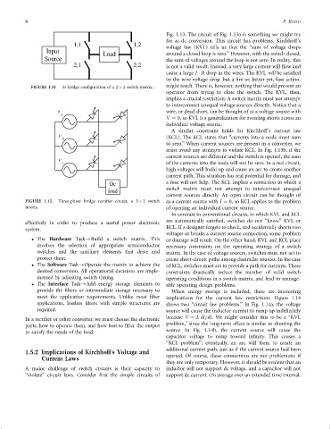
FIGURE 1.11 H-bridge con®guration of a 2 2 switch matrix.. might result. There is, however, nothing that would prevent an
operator from trying to close the switch. The KVL, then,
implies a crucial restriction: A switch matrix must not attempt
to interconnect unequal voltage sources directly. Notice that a
v wire, or dead short, can be thought of as a voltage source with
a
V ¼ 0, so KVL is a generalization for avoiding shorts across an
individual voltage source.
A similar constraint holds for Kirchhoff's current law
v
b (KCL). The KCL states that ‘‘currents into a node must sum
to zero.'' When current sources are present in a converter, we
must avoid any attempts to violate KCL. In Fig. 1.13b, if the
current sources are different and the switch is opened, the sum
v
c of the currents into the node will not be zero. In a real circuit,
high voltages will build up and cause an arc to create another
current path. This situation has real potential for damage, and
Dc a fuse will not help. The KCL implies a restriction in which a
switch matrix must not attempt to interconnect unequal
load
current sources directly. An open circuit can be thought of
FIGURE 1.12 Three-phase bridge recti®er circuit, a 3 2 switch as a current source with I ¼ 0, so KCL applies to the problem
matrix. of opening an individual current source.
In contrast to conventional circuits, in which KVL and KCL
effectively in order to produce a useful power electronic are automatically satis®ed, switches do not ‘‘know'' KVL or
system. KCL. If a designer forgets to check, and accidentally shorts two
voltages or breaks a current source connection, some problem
The Hardware Task!Build a switch matrix. This or damage will result. On the other hand, KVL and KCL place
involves the selection of appropriate semiconductor necessary constraints on the operating strategy of a switch
switches and the auxiliary elements that drive and matrix. In the case of voltage sources, switches must not act to
protect them. create short-circuit paths among dissimilar sources. In the case
The Software Task!Operate the matrix to achieve the of KCL, switches must act to provide a path for currents. These
desired conversion. All operational decisions are imple- constraints drastically reduce the number of valid switch
mented by adjusting switch timing. operating conditions in a switch matrix, and lead to manage-
The Interface Task!Add energy storage elements to able operating design problems.
provide the ®lters or intermediate storage necessary to When energy storage is included, there are interesting
meet the application requirements. Unlike most ®lter implications for the current law restrictions. Figure 1.14
applications, lossless ®lters with simple structures are shows two ‘‘circuit law problems.'' In Fig. 1.14a, the voltage
required. source will cause the inductor current to ramp up inde®nitely
because V ¼ Ldi=dt. We might consider this to be a ‘‘KVL
In a recti®er or other converter, we must choose the electronic
problem,'' since the long-term effect is similar to shorting the
parts, how to operate them, and how best to ®lter the output
source. In Fig. 1.14b, the current source will cause the
to satisfy the needs of the load.
capacitor voltage to ramp toward in®nity. This causes a
‘‘KCL problem''; eventually, an arc will form to create an
additional current path, just as if the current source had been
1.5.2 Implications of Kirchhoff's Voltage and
Current Laws opened. Of course, these connections are not problematic if
they are only temporary. However, it should be evident that an
A major challenge of switch circuits is their capacity to inductor will not support dc voltage, and a capacitor will not
‘‘violate'' circuit laws. Consider ®rst the simple circuits of support dc current. On average over an extended time interval,