
Page 28 - Rashid, Power Electronics Handbook
P. 28
1 Introduction 11
TABLE 1.2 The types of restricted switches
Action Device Quadrants Restricted Switch Symbol Device Symbol
Carries current in one direction, blocks in Diode
the other (forward-conducting
reverse-blocking)
Carries or blocks current in one direction BJT
(forward-conducting, forward-blocking)
Carries in one direction or blocks in both GTO
directions (forward-conducting,
bidirectional-blocking)
Carries in both directions, but blocks only in FET
one direction (bidirectional-carrying,
forward-blocking)
Fully bidirectional Ideal switch
sented with a discrete-valued switching function, the timing the operating frequencies are often dictated by the
can be represented within the switching function framework. application.
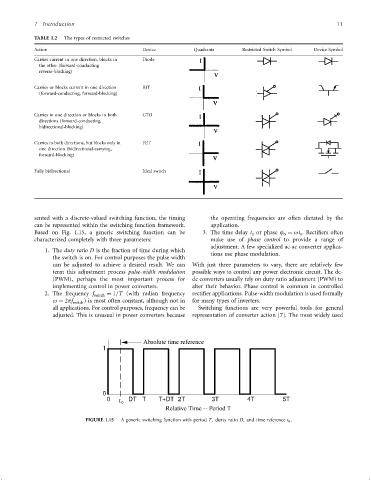
Based on Fig. 1.15, a generic switching function can be 3. The time delay t or phase f ¼ ot . Recti®ers often
0 0 0
characterized completely with three parameters: make use of phase control to provide a range of
adjustment. A few specialized ac-ac converter applica-
1. The duty ratio D is the fraction of time during which
tions use phase modulation.
the switch is on. For control purposes the pulse width
can be adjusted to achieve a desired result. We can With just three parameters to vary, there are relatively few
term this adjustment process pulse-width modulation possible ways to control any power electronic circuit. The dc-
(PWM), perhaps the most important process for dc converters usually rely on duty ratio adjustment (PWM) to
implementing control in power converters. alter their behavior. Phase control is common in controlled
2. The frequency f switch ¼ 1=T (with radian frequency recti®er applications. Pulse-width modulation is used formally
o ¼ 2pf switch ) is most often constant, although not in for many types of inverters.
all applications. For control purposes, frequency can be Switching functions are very powerful tools for general
adjusted. This is unusual in power converters because representation of converter action [7]. The most widely used
Absolute time reference
1
0
0 DT T T+DT 2T 3T 4T 5T
t 0
Relative Time -- Period T
FIGURE 1.15 A generic switching function with period T; durty ratio D; and time reference t 0 :