
Page 32 - Rashid, Power Electronics Handbook
P. 32
16 A. I. Maswood
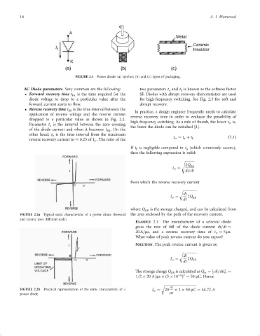
A
Metal
Ceramic
I F Insulator
K
(a) (b) (c)
FIGURE 2.1 Power diode: (a) symbol; (b) and (c) types of packaging.
AC Diode parameters. Very common are the following: two parameters t and t is known as the softness factor
a
b
Forward recovery time t FR is the time required for the SF. Diodes with abrupt recovery characteristics are used
diode voltage to drop to a particular value after the for high-frequency switching. See Fig. 2.3 for soft and
forward current starts to ¯ow. abrupt recovery.
Reverse recovery time t is the time interval between the
RR In practice, a design engineer frequently needs to calculate
application of reverse voltage and the reverse current
reverse recovery time in order to evaluate the possibility of
dropped to a particular value as shown in Fig. 2.2.
high-frequency switching. As a rule of thumb, the lower t is,
Parameter t is the interval between the zero crossing rr
a the faster the diode can be switched [1].
of the diode current and when it becomes I . On the
RR
other hand, t is the time interval from the maximum t ¼ t þ t
b
reverse recovery current to 0:25 of I . The ratio of the rr a b ð2:1Þ
rr
If t is negligible compared to t (which commonly occurs),
a
b
then the following expression is valid:
s
2Q RR
t ¼
rr
di=dt
from which the reverse recovery current
r
di
I ¼ 2Q
rr RR
dt
where Q RR is the storage charged, and can be calculated from
FIGURE 2.2a Typical static characteristic of a power diode (forward the area enclosed by the path of the recovery current.
and reverse have different scale).
EXAMPLE 2.1 The manufacturer of a selected diode
gives the rate of fall of the diode current di=dt ¼
20 A=ms, and a reverse recovery time of t ¼ 5 ms.
rr
What value of peak reverse current do you expect?
SOLUTION. The peak reverse current is given as:
r
di
I ¼ 2Q RR
rr
dt
2
1
The storage charge Q is calculated as Q ¼ di=dtt ¼
RR rr 2 rr
ÿ6 2
1=2 20 A=ms ð5 10 Þ ¼ 50 mC. Hence
r
a
FIGURE 2.2b Practical representation of the static characteristic of a I ¼ 20 2 50 mC ¼ 44:72 A
rr
power diode. ms