
Page 37 - Rashid, Power Electronics Handbook
P. 37
2 The Power Diode 21
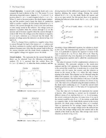
Circuit Operation A circuit with a single diode and a very driving function for the differential equation is the sinusoidal
common RL load is shown in Fig. 2.11. The source V is an function de®ning the source voltage. During the period
S
alternating sinusoidal source. Suppose V ¼ E sinðotÞ. V is de®ned by b < ot < 2p, the diode blocks the current and
S
S
m
positive when 0 < wt < p, and is negative when p < ot < 2p. acts as an open switch. For this period, there is no equation
When V starts to become positive, the diode begins conduct- de®ning the behavior of the circuit. For 0 < ot < b, Eq. (2.4)
S
ing and the positive source keeps the diode in conduction applies [7].
until ot reaches p radians. At that instant (de®ned by ot ¼ p
radians), the current through the circuit is not zero and there di þ R*i ¼ E* sinðyÞ; where ÿ 0 y b
is some energy stored in the inductor. The voltage across an L dt ð2:4Þ
inductor is positive when the current through it is on the
di
increase and it becomes negative when the current through it L þ R*i ¼ 0 ð2:5Þ
tends to fall. When the voltage across the inductor is negative, dt
it is in such a direction as to forward bias the diode. The di
oL þ R*i ¼ 0 ð2:6Þ
polarity of voltage across the inductor is as shown in Figs. 2.12 dy
and 2.13.
When V changes from a positive to a negative value, there ÿRy
S iðyÞ¼ A*e
is current through the load at the instant ot ¼ p radians and oL
the diode continues to conduct until the energy stored in the
Assuming a linear differential equation, the solution is found
inductor becomes zero. After that the current tends to ¯ow in
in two parts. The homogeneous equation is de®ned by Eq.
the reverse direction and the diode blocks conduction. The
(2.5). It is preferable to express the equation in terms of the
entire applied voltage now appears across the diode.
angle y instead of t.As y ¼ ot, then dy ¼ o:dt. Then Eq.
(2.5) is converted to Eq. (2.6). Equation (2.7) is the solution to
Circuit Analysis The expression for the current through the
this homogeneous equation and is called the complementary
diode can be obtained from the following mathematical
integral.
analysis [7]. It is assumed that the current ¯ows for
The value of constant A in the complementary solution is to
0 < ot < b, where b > p, when the diode conducts, and the
be calculated. The particular solution is the steady-state
response and Eq. (2.8) expresses it. The steady-state response
is the current that would ¯ow in steady-state in a circuit that
contains only the source, the resistor, and the inductor as
shown in the circuit in Fig. 2.11, where the only element
missing is the diode. This response can be obtained using the
differential equation, the Laplace transform, or the ac sinu-
soidal circuit analysis. The total solution is the sum of both the
complementary and the particular solution. It is shown in Eq.
(2.9). The value of A is obtained using the initial condition. As
the diode starts conducting at ot ¼ 0 and the current starts
building up from zero, ið0Þ¼ 0. The value of A is expressed by
Eq. (2.10).
FIGURE 2.12 Current rising, 0 < ot < p=2: Once the value of A is found, the expression for current
is known. After evaluating A, current can be evaluated at
different values of ot, starting from ot ¼ p.As wt increases,
the current continues to decrease. For some value of ot,say b,
the current would be zero. If ot > b, the current would drop
to a negative value. As the diode blocks current in the reverse
direction, the diode stops conducting when ot is reached.
Then an expression for the average output voltage can be
obtained. Because the average voltage across the inductor has
to be zero, the average voltage across the resistor and at the
cathode of the diode are the same. This average value can be
obtained as shown in Eq. (2.11).
E
iðyÞ¼ sinðot ÿ aÞ ð2:8Þ
FIGURE 2.13 Current falling, p=2 < ot < p. Z