
Page 41 - Rashid, Power Electronics Handbook
P. 41
2 The Power Diode 25
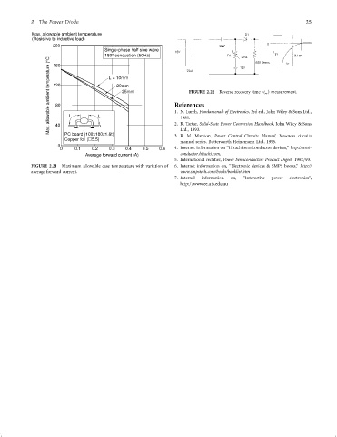
Max. allowable ambient temperature
(Resistive to inductive load)
200
Single-phase half sine wave
°
C) 160 180 conduction (50Hz)
Max. allowable ambient temperature (° 120 L L L = 10mm References Reverse recovery time (t rr ) measurement.
20mm
25mm
FIGURE 2.22
80
1. N. Lurch, Fundamenals of Electronics, 3rd ed., John Wiley & Sons Ltd.,
1981.
40
Ltd., 1993.
PC board (100 180 1.6t)
×
3. R. M. Marston, Power Control Circuits Manual, Newness circuits
Copper foil ( 5.5) × 2. R. Tartar, Solid-State Power Conversion Handbook, John Wiley & Sons
manual series. Butterworth Heinemann Ltd., 1995.
0
0 0.1 0.2 0.3 0.4 0.5 0.6 4. Internet information on ‘‘Hitachi semiconductor devices,'' http://semi-
Average forward current (A) conductor.hitachi.com.
5. International recti®er, Power Semiconductors Product Digest, 1992=93.
FIGURE 2.21 Maximum allowable case temperature with variation of 6. Internet information on, ‘‘Electronic devices & SMPS books,'' http://
average forward current. www.smpstech.com/books/booklist.htm
7. Internal information on, ‘‘Interactive power electronics'',
http:==www.ee.uts.edu.au