
Page 43 - Rashid, Power Electronics Handbook
P. 43
Hudgins
al.
et
J.
2828 J. Hudgins et al.
generally make use of power bipolar transistors, power Both SCRs and GTOs are designed to operate at all power
MOSFETs, or insulated gate bipolar transistors (IGBTs) as levels. These devices are primarily controlled using electrical
the main switching elements because of the relative ease in signals (current), although some types are made to be
controlling them. The IGBT technology, however, continues to controlled using optical (photons) energy for turn-on.
improve and multiple silicon die are commonly packaged Subclasses of SCRs and GTOs are reverse conducting types
together in a module. These modules are now replacing and symmetric structures that block applied potentials in the
thyristors in 1–3 kV applications because of easier gate-drive reverse and forward polarities. Other variations of GTOs are
requirements. Power diodes are used throughout all levels of the gate-commutated turn-off thyristor (GCT) and the bi-
power conditioning circuits and systems for component directional controlled thyristor (BCT). Most power converter
protection and wave-shaping. circuits that incorporate thyristors make use of either SCRs or
A thyristor used in some ac power circuits (50 or 60 Hz in GTOs, and hence this chapter will focus on these two devices,
commercial utilities or 400 Hz in aircraft) to control ac power although the basics of operation are applicable to all thyristor
¯ow can be made to optimize internal power loss at the types.
expense of switching speed. These thyristors are called All power electronic devices must be derated (e.g., power
phase-control devices because they are generally turned from dissipation levels, current conduction, voltage blocking, and
a forward-blocking into a forward-conducting state at some switching frequency must be reduced) when operating above
speci®ed phase angle of the applied sinusoidal anode-cathode room temperature (de®ned as 25 C). Bipolar-type devices
voltage waveform. A second class of thyristors is used in have thermal runaway problems, in that if allowed to conduct
association with dc sources or in converting ac power at one unlimited current, these devices will heat up internally, caus-
amplitude and frequency into ac power at another amplitude ing more current to ¯ow, thus generating more heat, and so
and frequency, and must generally switch on and off relatively forth until destruction. Devices that exhibit this behavior are
quickly. A typical application for this second class of thyristors pin diodes, bipolar transistors, and thyristors.
is that of converting a dc voltage or current into an ac voltage Almost all power semiconductor devices are made from
or current. A circuit that performs this operation is often silicon (Si), but some limited commercial devices are available
called an inverter, and the associated thyristors used are using gallium-arsenide (GaAs), and silicon-carbide SiC. The
referred to as inverter thyristors. latter two semiconductor material systems will not be directly
There are four major types of thyristors: i) silicon- discussed because of the lack of availability and usage. The
controlled recti®er (SCR); ii) gate turn-off thyristor (GTO); physical description and general behavior of thyristors are
iii) MOS-controlled thyristor (MCT) and its various forms; unimportant to the semiconductor material system used
and iv) static induction thyristor (SITh). The MCTs are so- although the discussion and any numbers cited in the chapter
named because many parallel enhancement-mode MOSFET will be associated with Si devices.
structures of one charge type are integrated into the thyristor
for turn-on and many more MOSFETs of the other charge
type are integrated into the thyristor for turn-off. These MCTs 3.2 Basic Structure and Operation
are currently limited to operation at medium power levels.
Other types of integrated MOS-thyristor structures can be
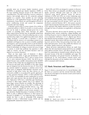
Figure 3.1 shows a conceptual view of a typical thyristor with
operated at high power levels, but these devices are not
the three p-n junctions and the external electrodes labeled.
commonly available or are produced for speci®c applications.
Also shown in the ®gure is the thyristor circuit symbol used in
A static induction thyristor (SITh), or ®eld-controlled thyr-
electrical schematics.
istor (FCTh), has essentially the same construction as a power
diode with a gate structure that can pinch-off anode current Anode (A)
¯ow. High-power SIThs have a subsurface gate (buried-gate) A
structure to allow larger cathode areas to be utilized, and
hence larger current densities are possible. The advantage of p
using MCTs, derivative forms of the MCT, or SIThs is that J1 -
they are essentially voltage-controlled devices, (e.g., little n G
control current is required for turn-on or turn-off) and, J2 p
therefore, require simpli®ed control circuits attached to the J3 K
gate electrode. Detailed discussion of variations of MCTs and n +
SIThs as well as additional references on these devices are
discussed by Hudgins [1]. Less important types of thyristors
include the Triac (a pair of antiparallel SCRs integrated Cathode (K) Gate (G)
together to form a bidirectional current switch) and the FIGURE 3.1 Simple cross section of a typical thyristor and the
programmable unijunction transistor (PUT). associated electrical schematic symbols.