Page 39 - Rashid, Power Electronics Handbook
P. 39

2 The Power Diode                                                                                    23

                 2.7 Typical Applications of Diodes


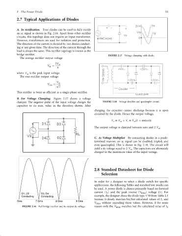
                 A. In recti®cation.  Four diodes can be used to fully rectify
                 an ac signal as shown in Fig. 2.16. Apart from other recti®er
                 circuits, this topology does not require an input transformer.
                 However, transformers are used for isolation and protection.
                 The direction of the current is decided by two diodes conduct-
                 ing at any given time. The direction of the current through the
                 load is always the same. This recti®er topology is known as the
                 bridge recti®er.                                              FIGURE 2.17  Voltage clamping with diode.
                   The average recti®er output voltage
                                           2V m
                                      V ¼
                                       dc
                                             p
                 where V is the peak input voltage.
                        m
                   The rms recti®er output voltage
                                            V m
                                      V   ¼ p
                                       rms    
                                              2
                 This recti®er is twice as ef®cient as a single-phase recti®er.

                 B. For Voltage Clamping.  Figure 2.17 shows a voltage
                 clamper. The negative pulse of the input voltage charges the  FIGURE 2.18  Voltage doubler and quadrupler circuit.
                 capacitor to its max. value in the direction shown. After
                                                                      charging, the capacitor cannot discharge because it is open
                                                                      circuited by the diode. Hence the output voltage,

                                                                                  V ¼ V þ V ¼ V ð1 þ sinðotÞÞ
                                                                                   o    m   i    m
                                                                      The output voltage is clamped between zero and 2 V .
                                                                                                                 m

                                                                      C. As Voltage Multiplier  By connecting diodes in a prede-
                                                                      termined manner, an ac signal can be doubled, tripled, and
                                                                      even quadrupled. This is shown in Fig. 2.18. The circuit will
                                                                      yield a dc voltage equal to 2 V . The capacitors are alternately
                                                                                              m
                                                                      charged to the maximum value of the input voltage.


                                                                      2.8 Standard Datasheet for Diode
                                                                           Selection


                                                                      In order for a designer to select a diode switch for speci®c
                                                                      applications, the following Tables and standard test results can
                                                                      be used. A power diode is chosen primarily based on forward
                     D1, D2       D3, D4                              current (I ) and the peak inverse (V RRM ) voltage [5]. For
                                                                              F
                     Conducting   Conducting                          example, the designer chose the diode type V 30 from Table 2.1
                  Oms         7 Oms         8 Oms         9 Oms       because it closely matches his=her calculated values of I and
                                                                                                                    F
                                                                      V RRM  without exceeding those values. However, if for some
                     FIGURE 2.16  Full bridge recti®er and its output dc voltage.  reason only the V RRM  matches but the calculated value of I F
   34   35   36   37   38   39   40   41   42   43   44