
Page 35 - Rashid, Power Electronics Handbook
P. 35
2 The Power Diode 19
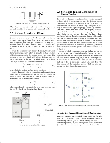
2.6 Series and Parallel Connection of
Power Diodes
For speci®c applications when the voltage or current rating of
a chosen diode is not enough to meet the designed rating,
FIGURE 2.6 The current waveform in Example 2.3. diodes can be connected in series or in parallel. Connecting
them in series will give the structure a high voltage rating that
2
These fuses are selected based on their I t rating, which is
may be necessary for high-voltage applications [2]. However,
normally speci®ed in a data sheet for a selected diode.
one must ensure that the diodes are properly matched,
especially in terms of their reverse recovery properties. Other-
2.5 Snubber Circuits for Diode wise, during reverse recovery there may be large voltage
unbalances between the series-connected diodes. Additionally,
Snubber circuits are essential for diodes used in switching due to differences in reverse recovery times, some diodes may
circuits. It can save a diode from overvoltage spikes, which recover from the phenomenon earlier than the others, thereby
may arise during the reverse recovery process. A very common causing them to bear the full reverse voltage. All of these
snubber circuit for a power diode consists of a capacitor and problems can effectively be overcome by connecting a bank of
a resistor connected in parallel with the diode as shown in a capacitor and a resistor in parallel with each diodes as shown
Fig. 2.7. in Fig. 2.8.
When the reverse recovery current decreases, the capacitor If a selected diode cannot match the required current rating,
by virtue of its property will try to retain the voltage across it, one may connect several diodes in parallel. In order to ensure
which is approximately the voltage across the diode. The equal current sharing, the designer must choose diodes with
resistor, on the other hand, will help to dissipate some of the same forward voltage drop properties. It is also important
the energy stored in the inductor, which forms the I loop.
rr to ensure that the diodes are mounted on similar heat sinks
The dv=dt across a diode can be calculated as: and are cooled (if necessary) equally. This will affect the
dv 0:632*V S 0:632*V S temperatures of the individual diodes, which in turn may
¼ ¼ ð2:2Þ change the diode forward characteristics.
dt t R *C S
S
where V is the voltage applied across the diode.
S
Usually the dv=dt rating of a diode is given in manufacturer
datasheets. By knowing dv=dt and R , one can choose the
S
value of the snubber capacitor C . Here R can be calculated
S
S
from the diode reverse recovery current:
V S
R ¼ ð2:3Þ
S
I rr
The designed dv=dt value must always be equal or lower than
the dv=dt value found from the data sheet.
FIGURE 2.8 Series-connected diodes with necessary protection.
Tutorial 2.1 Reverse Recovery and Overvoltages
Figure 2.9 shows a simple switch mode power supply. The
switch (1-2) is closed at t ¼ 0 S. When the switch is open, a
freewheeling current I ¼ 20 A ¯ows through the load (RL),
F
(a) (b) freewheeling diode (DF), and the large load circuit inductance
FIGURE 2.7 A typical snubber circuit. (LL). The diode reverse recovery current is 20 A and it then