Page 36 - Rashid, Power Electronics Handbook
P. 36

20                                                                                         A. I. Maswood

                                                                      from time zero to time t the current will decay at a rate
                                                                                          1
                                                                      of 20 A=S and will be zero at t ¼ 20=20 ¼ 1=mS. The
                                                                                                 1
                                                                      reverse recovery current starts at this point and accord-
                                                                      ing to the given condition becomes 20 A at t . From this
                                                                                                          2
                                                                      point on, the rate of change remains unchanged at
                                                                      20 A=mS. Period t ÿ t is found:
                                                                                     2
                                                                                        1
                                                                                            20 A
                                                                                   t ÿ t ¼        ¼ 1 mS
                                                                                       1
                                                                                   2
                                                                                           20 A=mS
                                                                      From t to t the current decays to zero at the rate of
                                                                            2
                                                                                 3
                                                                      20 A=mS. The required time is
                                                                                            20 A
                                                                                   t ÿ t ¼        ¼ 2 mS
               FIGURE 2.9  A simple switch mode power supply with freewheeling     3   2   10 A=mS
               diode.
                                                                      Hence the actual reverse recovery time: t ¼ t ÿ t ¼
                                                                                                         rr
                                                                                                                 1
                                                                                                             3
               decays to zero at the rate of 10 A=mS. The load is rated at 10 O  ð1 þ 1 þ 2Þÿ 1 ¼ 3 mS.
               and the forward on-state voltage drop is neglected.
                                                                        (b) The diode experiences the maximum voltage only
                   (a) Draw the current waveform during the reverse recov-  when the switch is open. This is due to both the source
                      ery (I ) and ®nd its time (t ).                 voltage 200 V and the newly formed voltage caused by
                           rr                rr
                   (b) Calculate the maximum voltage across the diode  the change in current through inductor L. The voltage
                       during this process (I ).                      across the diode,
                                        rr
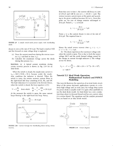
                  SOLUTION. (a) A typical current waveform during                   di
                                                                                                                 6
                                                                                                      ÿ6
                  reverse recovery process is shown in Fig. 2.10 for an  V ¼ÿV þ L  dt S  ¼ÿ200 þð10   10 Þðÿ20   10 Þ
                                                                         D
                  ideal diode.
                                                                           ¼ÿ400 V
                    When the switch is closed, the steady-state current is
                  I SS  ¼ 200 V=10 O ¼ 20 A, because under the steady-  Tutorial 2.2 Ideal Diode Operation,
                  state condition the inductor is shorted. When the              Mathematical Analysis and PSPICE
                  switch is open, the reverse recovery current ¯ows in           Modelling
                  the right-hand side loop consisting of LL, RL, and DF.
                  The load inductance LL is assumed to be shorted. Hence,  This tutorial illustrates the operation of an ideal diode circuit.
                  when the switch is closed, the loop equation is [3]:  Most of the power electronic applications operate at a rela-
                        di S             di S  V  200               tively high voltage and, in such cases, the voltage drop across
                   V ¼ L     from which     ¼   ¼    ¼ 20 A=mS      the power diode is usually small. It is quite often justi®able to
                         dt              dt   L   10
                                                                    use the ideal diode model. An ideal diode has a zero conduc-
                  At the moment the switch is open, the same current
                                                                    tion drop when it is forward-biased and has zero current when
                  keeps ¯owing in the right-hand side loop. Hence,
                                                                    it is reverse-biased. The equations and the analysis presented
                              di d  ¼ÿ  di S  ¼ÿ20 A=mS             here are based on an ideal diode model.
                               dt     dt


               FIGURE 2.10  Current through the freewheeling diode during reverse
               recovery.                                                          FIGURE 2.11  Circuit diagram.
   31   32   33   34   35   36   37   38   39   40   41