
Page 27 - Rashid, Power Electronics Handbook
P. 27
P. Krein
1010 P . Krein
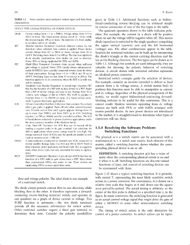
TABLE 1.1 Some modern semiconductor switch types and their basic given in Table 1.2. Additional functions such as bidirec-
characteristics tional-conducting reverse-blocking can be obtained simply
by reverse connection of one of the ®ve types in the table.
DEVICE TYPE CHARACTERISTICS OF POWER DEVICES
The quadrant operation shown in the table indicates pola-
Diode Current ratings from <1 to >5000 A. Voltage ratings from 10 V to rities. For example, the current in a diode will be positive
10 kV or more. The fastest power devices switch in <20 ns, while
when on and the voltage will be negative when off. This means
the slowest require 100 ms or more. The function of a diode applies
in recti®ers and dc-dc circuits. diode operation is restricted to the single quadrant comprising
BJT (Bipolar Junction Transistor) Conducts collector current (in one the upper vertical (current) axis and the left horizontal
direction) when suf®cient base current is applied. Power device (voltage) axis. The other combinations appear in the table.
current ratings from 0.5 to 500 A or more; voltages from 30 to Symbols for restricted switches can be built up by interpreting
1200 V. Switching times from 0.5 to 100 ms. The function applies to the diode's triangle as the current-carrying direction and the
dc-dc circuits; combinations with diodes are used in inverters.
Power BJTs are being supplanted by FETs and IGBTs. bar as the blocking direction. The ®ve types can be drawn as in
FET (Field Effect Transistor) Conducts drain current when suf®cient Table 1.2. Although the symbols are used infrequently, they are
gate voltage is applied. Power FETs (nearly always enhancement- valuable for showing the polarity behavior of switching
mode MOSFETs) have a parallel connected reverse diode by virtue devices. A circuit drawn with restricted switches represents
of their construction. Ratings from 1 to 100 A and 30 up to an idealized power converter.
1000 V. Switching times are fast, from 50 or less up to 200 ns. The
function applies to dc-dc conversion, where the FET is in wide use, Restricted switch concepts guide the selection of devices.
and to inverters. For example, consider an inverter intended to deliver ac load
IGBT (Insulated Gate Bipolar Transistor) A special type of power FET current from a dc voltage source. A switch matrix built to
that has the function of a BJT with its base driven by a FET. Faster perform this function must be able to manipulate ac current
than a BJT of similar ratings, and easy to use. Ratings from 10 to and dc voltage. Regardless of the physical arrangement of the
>600 A, with voltages of 600 to 1700 V. The IGBT is popular in
matrix, we would expect bidirectional-conducting forward-
inverters from 1 to 100 kW or more. It is found almost exclu-
sively in power electronics applications. blocking switches to be useful for this conversion. This is a
SCR (Silicon Controlled Recti®er) A thyristor that conducts like a diode correct result: Modern inverters operating from dc voltage
after a gate pulse is applied. Turns off only when current becomes sources are built with FETs or with IGBTs arranged with
zero. Prevents current ¯ow until a pulse appears. Ratings from 10
reverse-parallel diodes. As new power devices are introduced
up to more than 5000 A, and from 200 V up to 6 kV. Switching
to the market, it is straightforward to determine what types of
requires 1 to 200 ms. Widely used for controlled recti®ers. The SCR
is found almost exclusively in power electronics applications, and is converters will use them.
the most common member of the thyristor family.
GTO (Gate Turn-Off Thyristor) An SCR that can be turned off by
sending a negative pulse to its gate terminal. Can substitute for 1.5.4 Resolving the Software Problem:
BJTs in applications where power ratings must be very high. The Switching Functions
ratings approach those of SCRs, and the speeds are similar as well.
Used in inverters rated >100 kW. The physical m n switch matrix can be associated with a
TRIAC A semiconductor constructed to resemble two SCRs connected in mathematical m n switch state matrix. Each element of this
reverse parallel. Ratings from 2 to 50 A and 200 to 800 V. Used in matrix, called a switching function, shows whether the corre-
lamp dimmers, home appliances, and hand tools. Not as rugged as sponding physical device is on or off.
many other device types, but very convenient for many ac applica-
tions. DEFINITION: A switching function qðtÞ has a value of
MCT (MOSFET Controlled Thyristor) A special type of SCR that has the unity when the corresponding physical switch is on and
function of a GTO with its gate driven from a FET. Much faster
than conventional GTOs, and easier to use. These devices are 0 when it is off. Switching functions are discrete-valued
supplanting GTOs in some application areas. functions of time, and control of switching devices can
be represented with them.
Figure 1.15 shows a typical switching function. It is periodic,
with period T, representing the most likely repetitive switch
¯ow and voltage polarity. The ideal diode is one example
action in a power converter. For convenience, it is drawn on a
of a restricted switch.
relative time scale that begins at 0 and draws out the square
The diode always permits current ¯ow in one direction, while wave period-by-period. The actual timing is arbitrary, so the
blocking ¯ow in the other. It therefore represents a forward- center of the ®rst pulse is de®ned as a speci®ed time t in the
0
conducting reverse-blocking restricted switch, and operates in ®gure. In many converters, the switching function is generated
one quadrant on a graph of device current vs voltage. This as an actual control voltage signal that might drive the gate of
FCRB function is automatic Ð the two diode terminals either a MOSFET or some other semiconductor switching
provide all the necessary information for switch action. device.
Other restricted switches require a third gate terminal to The timing of switch action is the only alternative for
determine their state. Consider the polarity possibilities control of a power converter. As switch action can be repre-