
Page 23 - Rashid, Power Electronics Handbook
P. 23
P. Krein
66 P . Krein
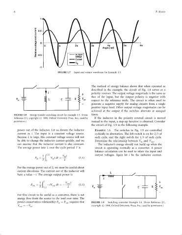
FIGURE 1.7 Input and output waveforms for Example 1.5.
The method of energy balance shows that when operated as
described in the example, the circuit of Fig. 1.8 serves as a
polarity reverser. The output voltage magnitude is the same as
that of the input, but the output polarity is negative with
respect to the reference node. The circuit is often used to
generate a negative supply for analog circuits from a single
positive input level. Other output voltage magnitudes can be
achieved at the output if the switches alternate at unequal
FIGURE 1.8 Energy transfer switching circuit for Example 1.5. (From times.
Reference [2], copyright # 1998, Oxford University Press, Inc.; used by If the inductor in the polarity reversal circuit is moved
permission.) instead to the input, a step-up function is obtained. Consider
the circuit of Fig. 1.9 in the following example.
power out of the inductor. Let us denote the inductor EXAMPLE 1.6. The switches in Fig. 1.9 are controlled
current as i. The input is a constant voltage source. cyclically in alternation. The left switch is on for 2=3of
Because L is large, this constant voltage source will not each cycle, and the right switch for 1=3 of each cycle.
be able to change the inductor current quickly, and we Determine the relationship between V and V out .
in
can assume that the inductor current is also constant. The inductor's energy should not build up when the
The average power into L over the cycle period T is circuit is operating normally as a converter. A power
balance calculation can be used to relate the input and
ð T=2 output voltages. Again let i be the inductor current.
1 V i
in
P ¼ V idt ¼ ð1:4Þ
in in
T 0 2
For the average power out of L, we must be careful about
current directions. The current out of the inductor will
have a value ÿi. The average output power is
ð T
1 V out i
P out ¼ ÿiV out dt ¼ÿ ð1:5Þ
T T=2 2
For this circuit to be useful as a converter, there is net
energy ¯ow from the source to the load over time. The
power conservation relationship P ¼ P out requires that FIGURE 1.9 Switching converter Example 1.6. (From Reference [2],
in
V out ¼ÿV . copyright # 1998, Oxford University Press, Inc.; used by permission.)
in