
Page 26 - Rashid, Power Electronics Handbook
P. 26
1 Introduction 9
(a) (b)
I
2
V ac Switch V dc I 1 Switch
must remain must remain
open closed
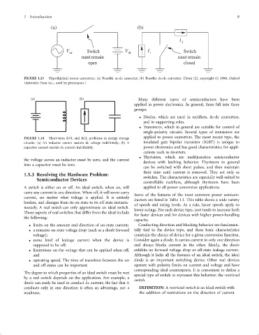
FIGURE 1.13 Hypothjetical power converters: (a) Possible ac-dc converter; (b) Possible dc-dc converter. (From [2], copyright # 1998, Oxford
University Press Inc., used by permission.)
(a) (b) Many different types of semiconductors have been
applied in power electronics. In general, these fall into three
groups:
Diodes, which are used in recti®ers, dc-dc converters,
and in supporting roles.
Transistors, which in general are suitable for control of
single-polarity circuits. Several types of transistors are
applied to power converters. The most recent type, the
FIGURE 1.14 Short-term KVL and KCL problems in energy storage
circuits: (a) An inductor cannot sustain dc voltage inde®nitely; (b) A insulated gate bipolar transistor (IGBT) is unique to
capacitor cannot sustain dc current inde®nitely. power electronics and has good characteristics for appli-
cations such as inverters.
Thyristors, which are multijunction semiconductor
the voltage across an inductor must be zero, and the current
devices with latching behavior. Thyristors in general
into a capacitor must be zero.
can be switched with short pulses, and then maintain
their state until current is removed. They act only as
1.5.3 Resolving the Hardware Problem:
Semiconductor Devices switches. The characteristics are especially well-suited to
controllable recti®ers, although thyristors have been
A switch is either on or off. An ideal switch, when on, will applied to all power conversion applications.
carry any current in any direction. When off, it will never carry
Some of the features of the most common power semicon-
current, no matter what voltage is applied. It is entirely
ductors are listed in Table 1.1. This table shows a wide variety
lossless, and changes from its on state to its off state instanta-
of speeds and rating levels. As a rule, faster speeds apply to
neously. A real switch can only approximate an ideal switch.
lower ratings. For each device type, cost tends to increase both
Those aspects of real switches that differ from the ideal include
for faster devices and for devices with higher power-handling
the following:
capacity.
limits on the amount and direction of on-state current; Conducting direction and blocking behavior are fundamen-
a nonzero on-state voltage drop (such as a diode forward tally tied to the device type, and these basic characteristics
voltage); constrain the choice of device for a given conversion function.
some level of leakage current when the device is Consider again a diode. It carries current in only one direction
supposed to be off; and always blocks current in the other. Ideally, the diode
limitations on the voltage that can be applied when off; exhibits no forward voltage drop or off-state leakage current.
and Although it lacks all the features of an ideal switch, the ideal
operating speed. The time of transition between the on diode is an important switching device. Other real devices
and off states can be important. operate with polarity limits on current and voltage and have
corresponding ideal counterparts. It is convenient to de®ne a
The degree to which properties of an ideal switch must be met
special type of switch to represent this behavior: the restricted
by a real switch depends on the application. For example, a
switch.
diode can easily be used to conduct dc current; the fact that it
conducts only in one direction is often an advantage, not a DEFINITION: A restricted switch is an ideal switch with
weakness. the addition of restrictions on the direction of current