
Page 111 - Renewable Energy Devices and System with Simulations in MATLAB and ANSYS
P. 111
98 Renewable Energy Devices and Systems with Simulations in MATLAB and ANSYS ®
®
where k, k −1 are consecutive time steps, α> 0 is a constant determining the speed of convergence
⋅
to the MPP, and the function sign() is defined as follows:
1 if x > 0
sign( ) x = (5.5)
−1 if x < 0
The PV module/array output voltage is regulated to the desired value, which is determined by V ref
according to (5.4), using either a proportional integral (PI) or, for example, a fuzzy logic controller.
The latter has the advantage of providing a better response under dynamic conditions [25]. Under
steady-state conditions, the operating point of the PV module/array oscillates around the MPP with
an amplitude determined by the value of α in (5.4). Increasing the perturbation step enables to con-
verge faster to the MPP under changing solar irradiation and/or ambient temperature conditions but
increases the steady-state oscillations around the MPP, thus resulting in power loss.
An MPPT system based on the P&O method can be developed by either implementing (5.4)
in the form of an algorithm executed by a microcontroller or digital signal processing (DSP) unit
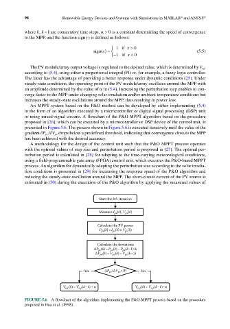
or using mixed-signal circuits. A flowchart of the P&O MPPT algorithm based on the procedure
proposed in [26], which can be executed by a microcontroller or DSP device of the control unit, is
presented in Figure 5.6. The process shown in Figure 5.6 is executed iteratively until the value of the
gradient ∂ ∂P pv / V pv drops below a predefined threshold, indicating that convergence close to the MPP
has been achieved with the desired accuracy.
A methodology for the design of the control unit such that the P&O MPPT process operates
with the optimal values of step size and perturbation period is proposed in [27]. The optimal per-
turbation period is calculated in [28] for adapting to the time-varying meteorological conditions,
using a field-programmable gate array (FPGA) control unit, which executes the P&O-based MPPT
process. An algorithm for dynamically adapting the perturbation size according to the solar irradia-
tion conditions is presented in [29] for increasing the response speed of the P&O algorithm and
reducing the steady-state oscillation around the MPP. The short-circuit current of the PV source is
estimated in [30] during the execution of the P&O algorithm by applying the measured values of
Start the kth iteration
(k), V (k)
Measure I pv pv
Calculate the PV power
P (k)= I (k)×V (k)
pv
pv
pv
Calculate the deviations
(k)= P (k)–P (k–1) &
P pv pv pv
V (k)= V (k)–V (k–1)
pv
pv
pv
Yes P pv / V >0? No
pv
V (k)= V (k–1)+ α V (k)=V (k–1)–α
ref
ref
ref
ref
FIGURE 5.6 A flowchart of the algorithm implementing the P&O MPPT process based on the procedure
proposed in Hua et al. (1998).