
Page 114 - Renewable Energy Devices and System with Simulations in MATLAB and ANSYS
P. 114
Overview of PV Maximum Power Point Tracking Techniques 101
MPPT subsystem operating according to the InC method is added to the output of a model-based
MPP tracker, thus forming a hybrid MPPT controller.
The model-based MPPT techniques have the advantage of not disconnecting the PV source
during the execution of the MPPT process. The accuracy of the model-based MPPT method is
affected by the accuracy of the single-diode model of the PV source, as well as by the aging of the
PV modules, which results in the modification of the values of the PV module operating parameters
during the PV system operational lifetime period.
5.3.5 Artificial Intelligence–Based MPPT
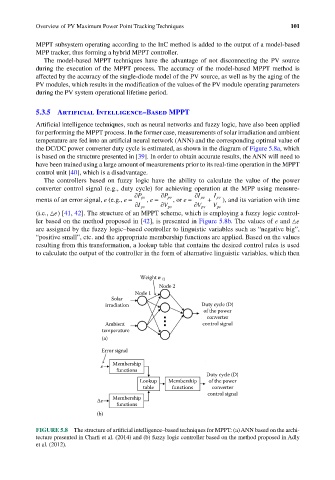
Artificial intelligence techniques, such as neural networks and fuzzy logic, have also been applied
for performing the MPPT process. In the former case, measurements of solar irradiation and ambient
temperature are fed into an artificial neural network (ANN) and the corresponding optimal value of
the DC/DC power converter duty cycle is estimated, as shown in the diagram of Figure 5.8a, which
is based on the structure presented in [39]. In order to obtain accurate results, the ANN will need to
have been trained using a large amount of measurements prior to its real-time operation in the MPPT
control unit [40], which is a disadvantage.
The controllers based on fuzzy logic have the ability to calculate the value of the power
converter control signal (e.g., duty cycle) for achieving operation at the MPP using measure-
∂ ∂ ∂
ments of an error signal, e (e.g., e = P pv , e = P pv , or e = I pv + I pv ), and its variation with time
∂ I pv ∂ V pv ∂ V pv V pv
(i.e., e) [41, 42]. The structure of an MPPT scheme, which is employing a fuzzy logic control-
ler based on the method proposed in [42], is presented in Figure 5.8b. The values of e and e
are assigned by the fuzzy logic–based controller to linguistic variables such as “negative big”,
“positive small”, etc. and the appropriate membership functions are applied. Based on the values
resulting from this transformation, a lookup table that contains the desired control rules is used
to calculate the output of the controller in the form of alternative linguistic variables, which then
Weight w 12
Node 2
Node 1
Solar
irradiation Duty cycle (D)
of the power
converter
Ambient control signal
temperature
(a)
Error signal
e Membership
functions
Duty cycle (D)
Lookup Membership of the power
table functions converter
control signal
Membership
∆e
functions
(b)
FIGURE 5.8 The structure of artificial intelligence–based techniques for MPPT: (a) ANN based on the archi-
tecture presented in Charfi et al. (2014) and (b) fuzzy logic controller based on the method proposed in Adly
et al. (2012).