
Page 234 - Renewable Energy Devices and System with Simulations in MATLAB and ANSYS
P. 234
Electric Generators and their Control for Large Wind Turbines 221
I (kA)
s
15
10
5
0
–5
–10
–15
(a)
I s (kA)
3
2
1
0
–1
–3
(b)
(rad/s)
ω r
190
180
170
160
(c)
T turbine (kNm)
11.8
11.4
11.0
10.6
(d)
(kNm)
T DFIG
100
80
60
40
20
0
–20
2.8 3 3.2 3.4 3.6 3.8 4
(e) Time (s)
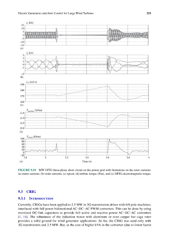
FIGURE 9.10 MW DFIG three-phase short circuit on the power grid with limitations on the rotor currents:
(a) stator currents, (b) rotor currents, (c) speed, (d) turbine torque (Nm), and (e) DFIG electromagnetic torque.
9.3 CRIG
9.3.1 Introduction
Currently, CRIGs have been applied to 2.5 MW in 3G transmission drives with 6/8 pole machines,
interfaced with full power bidirectional AC–DC–AC PWM converters. This can be done by using
oversized DC-link capacitors to provide full active and reactive power AC–DC–AC converters
[1, 14]. The robustness of the induction motor with aluminum or even copper bar cage rotor
provides a solid ground for wind generator applications. So far, the CRIG was used only with
3G transmission and 2.5 MW. But, at the cost of higher kVA in the converter (due to lower factor