
Page 236 - Renewable Energy Devices and System with Simulations in MATLAB and ANSYS
P. 236
Electric Generators and their Control for Large Wind Turbines 223
Machine-side Grid-side
Blade converter converter
DC link
Gearbox Grid
CRIG
Filter
ω r
i abcs v abcs PWM V DC PWM
i abc
v abc
P* grid Control center
*
Turbine angle Q grid V* DC
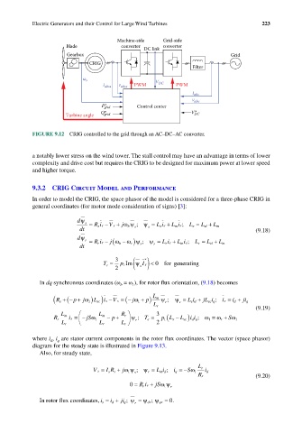
FIGURE 9.12 CRIG controlled to the grid through an AC–DC–AC converter.
a notably lower stress on the wind tower. The stall control may have an advantage in terms of lower
complexity and drive cost but requires the CRIG to be designed for maximum power at lower speed
and higher torque.
9.3.2 CRIG Circuit Model and Performance
In order to model the CRIG, the space phasor of the model is considered for a three-phase CRIG in
general coordinates (for motor mode consideration of signs) [3]:
dψ s = R is − V s + jωψ ; ψ = L is + L ir; L s = L sl +
dt s b s s s m L m (9.18)
dψ r = R ir − ( ψ = L L L
j ω
r r
r
dt r b ω− )ψ ; r r r i + m s i ; r L = rl L + m
3 *
T e = p 1 Im ψ s ( )
I s < 0 forgenerating
2
In dq synchronous coordinates (ω = ω ), for rotor flux orientation, (9.18) becomes
1
b
( R s +− + j ) ) − V s = − ( jω 1 + p) L m ψ ; ψ s = Li sd + jL i q ; is = i d + jji q
(
p
is
ω 1
L sc
sc
r
L r
(9.19)
R r 3
L m L m ( L sc)
ω
p
R r is =− jSω 1 −+ ψ ; T e = p L s − ii ; ω 1 = ω + S ω 1
r
1
dq
r
L r L r L r 2
where i , i are stator current components in the rotor flux coordinates. The vector (space phasor)
d
q
diagram for the steady state is illustrated in Figure 9.13.
Also, for steady state,
V s = IR s + jωψ ; ψ r = L i d ; i q = − Sω 1 L r i d
1
s
m
s
R r (9.20)
0 = R r ir + jSωψ r
1
In rotor flux coordinates, i s = i d + ji q ; ψ r = ψ dr ; ψ qr = 0.