
Page 235 - Renewable Energy Devices and System with Simulations in MATLAB and ANSYS
P. 235
222 Renewable Energy Devices and Systems with Simulations in MATLAB and ANSYS ®
®
power), CRIGs may be used at lower speeds with 1G transmission (up to 10/1 ratio). Typically, a
CRIG should be characterized by the following:
• High efficiency and moderate power factor for rated (middle) speed.
• Small leakage inductances, to secure large peak power reserve.
• Stator coils and rotor bars should experience limited skin and proximity effect, to limit the
additional winding losses.
The CRIG should be designed to fit the WT characteristics P (ω ), ω —generator speed.
r
t
r
The flattop power/speed characteristic is obtained by modifying the power efficiency coefficient
C of the turbine, essentially by changing the turbine blade angle β via controlled servomotors while
p
following the maximum power tracking methods when they reach maximum power. The pitch-
regulated turbine keeps the generator turbine speed and torque constant, while for the stall-regulated
turbine, the rotor speed increases further a bit with torque, for constant (peak) power. Essentially,
*
*
the input wind speed v leads to a certain reference torque generator T e for a certain speed ω r (and
w
*
*
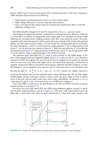
power P ), for the envelope curve shown in Figure 9.11. When the required power P e is less than the
*
envelope power in Figure 9.11, being dictated by the power grid, again, P e may be regulated to yield
*
*
T e (or ω r ) and thus torque or speed regulation in the CRIG is executed.
*
*
The generator speed and torque (ω r , T e ) range is quite essential for the CRIG design. It dif-
*
*
fers in stall-regulated and pitch-regulated turbines (Figure 9.11). But not only T e (or ω r ) should be
regulated in CRIG, the magnetic flux ψ level should also be regulated and in general be operated
m
with low total losses (core losses and copper losses). In a stand-alone operation, a certain level of
*
magnetic saturation in CRIG is required for self-excitation. Either the rotor flux linkage ψ r or stator
*
*
*
flux linkage ψ s can be regulated versus speed ω r (and T e ). One more factor to be considered is the
*
*
*
fact that the emf E r1 = ω * 1 L m * r ψ or E s1 = ωψ * s ω; 1 = ω r + Sω should vary slightly with power,
1
1
L r
to operate the machine-side converter optimally in the voltage-boosting mode. The DC-link voltage
should slightly increase with power (speed), which is above the grid voltage in order to deliver
*
*
power to the grid with low total system losses and to help controllability. So planning ψ r (or ψ s )
*
*
versus speed ω r and P e is not a trivial task in the case of CRIGs for wind power.
Now if the CRIG is connected to the grid through an AC–DC–AC PWM converter, its generic
control structure is as in Figure 9.12.
In essence, for active stall control WTs, the CRIG design bottleneck appears in points A and B
S
S
and for pitch control in points A and B in Figure 9.11. The active stall control tends to place the
P
P
blades like “a wall in the wind,” while the pitch control leads to “a flag in the wind” situation, with
P t P
T* e 1-Active stall or turbine 1
ω* r pitch control 2
2-Passive stall
control 2 B
B p T* e S
1
A p ω r * 1
2 A S v W
Cut-in Cutoff
FIGURE 9.11 Generic WT characteristics: generator power, speed, and torque versus wind speed.